

Connector for domed cutting tool
- Summary
- Abstract
- Description
- Claims
- Application Information
AI Technical Summary
Benefits of technology
Problems solved by technology
Method used
Image

Examples
Embodiment Construction
)
[0055] During surgery for preparation of a joint for installation of a joint prosthesis, it has become important to capture and preserve the tissue and debris removed from a joint for later use. However, conventional surgical tools with hollow cutting heads that are typically used for this type of surgery commonly have cup-shaped cutting edge projections that are relatively thin, become dull relatively rapidly during use, and are not readily sharpened or replaced, so that once the cutting edges of the surgical tool become dull, the surgical tool is useless.
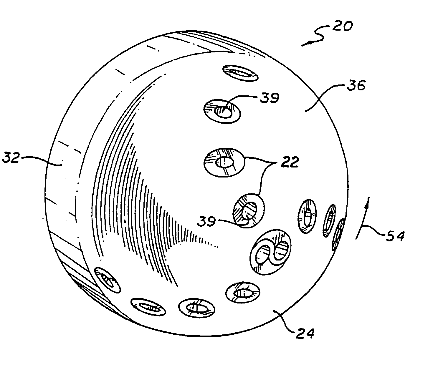
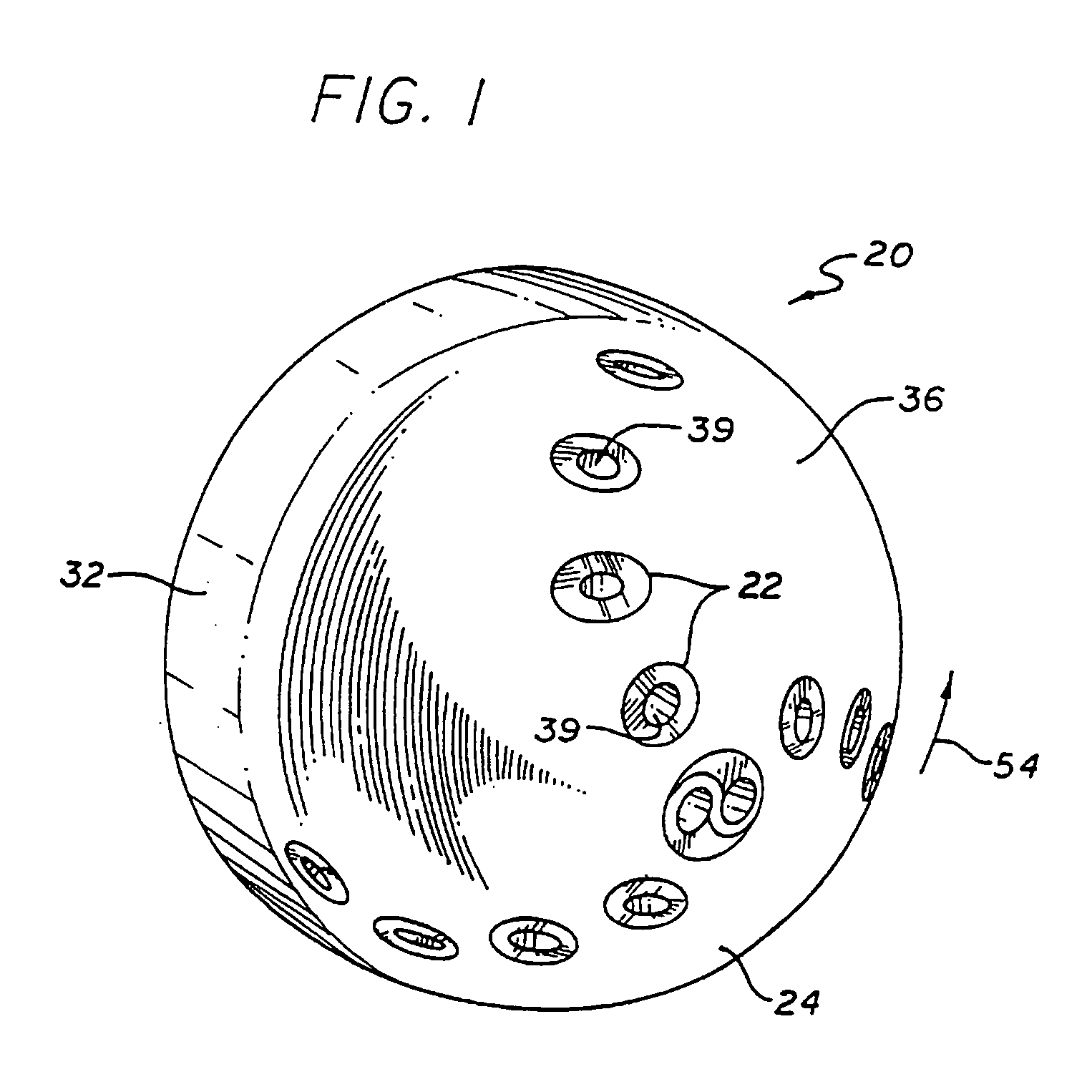
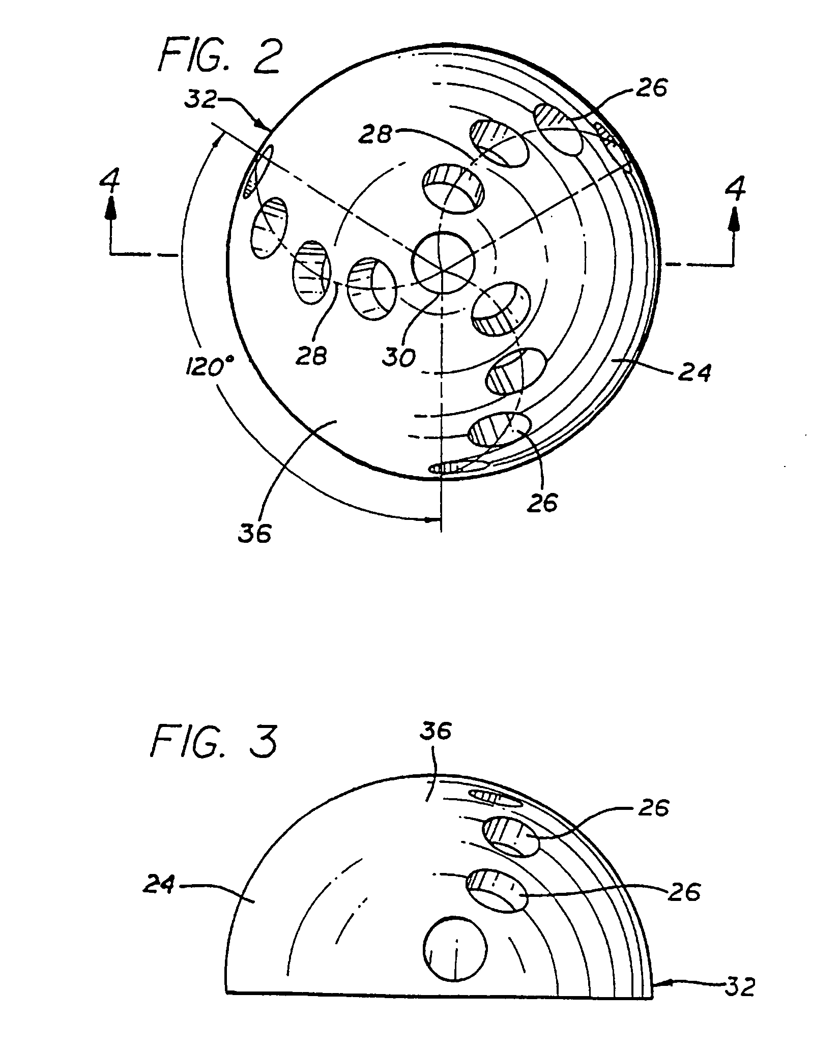
[0056] As is illustrated in the drawings, the invention is accordingly embodied in a hollow dome reamer that provides greater cutting accuracy, with removable teeth having superior cutting edges. The removable teeth can readily be replaced, and resharpened for repeated usage. Referring to FIGS. 1 through 11, the hollow dome reamer 20 is preferably a rotary surgical reamer having a plurality of inserted modular teeth 22 or cutter...
PUM
 Abstract
Description
Claims
Application Information