[0014] The present invention will be further described below in conjunction with the drawings and embodiments.
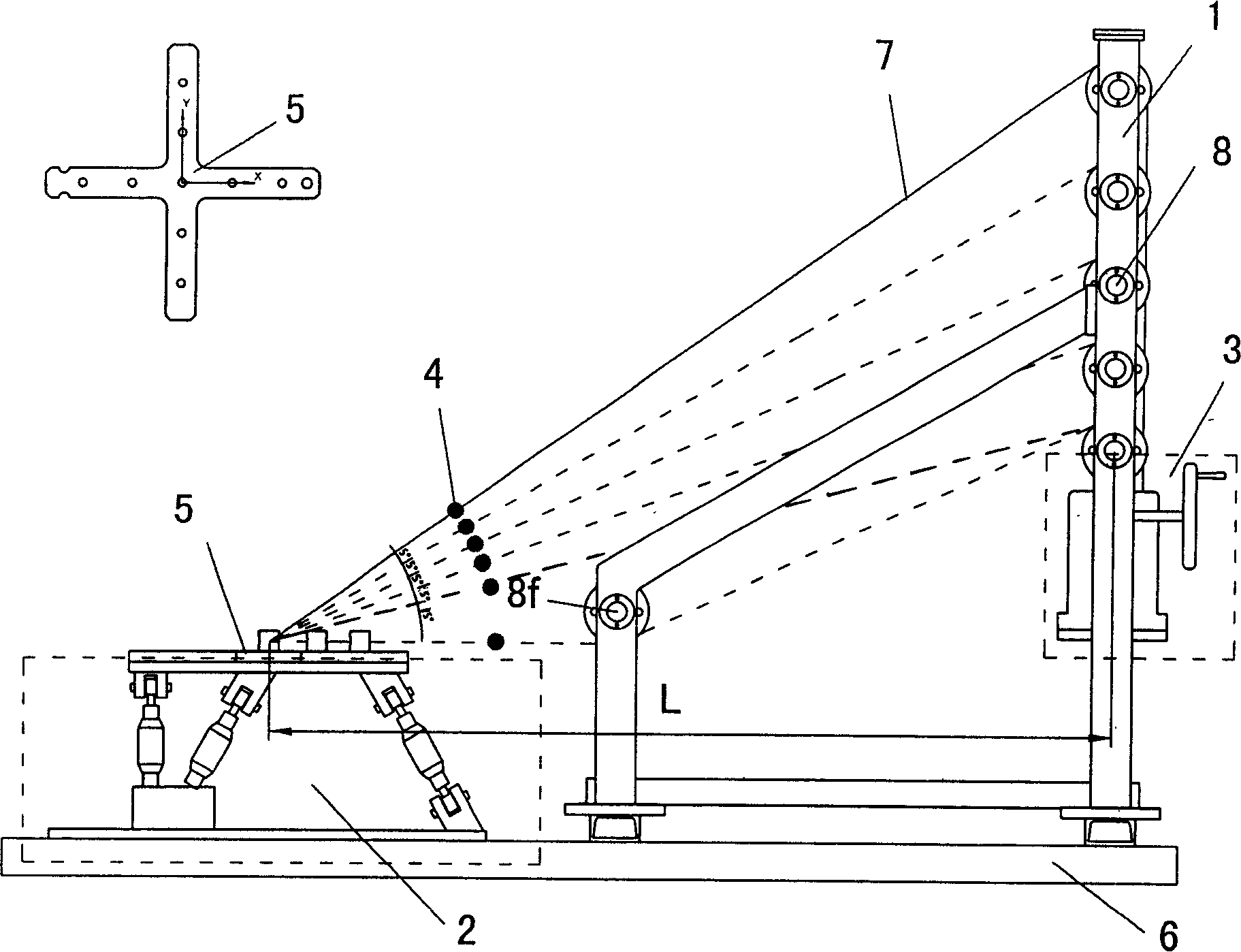
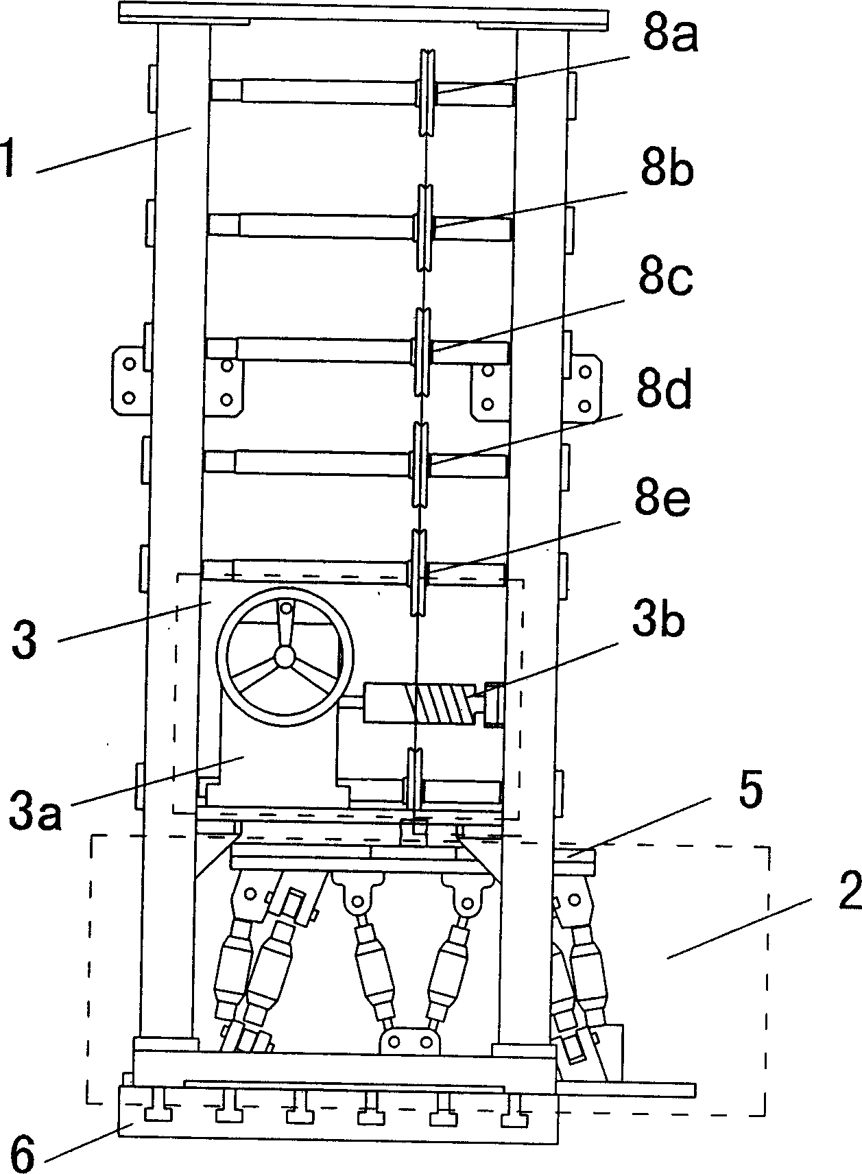
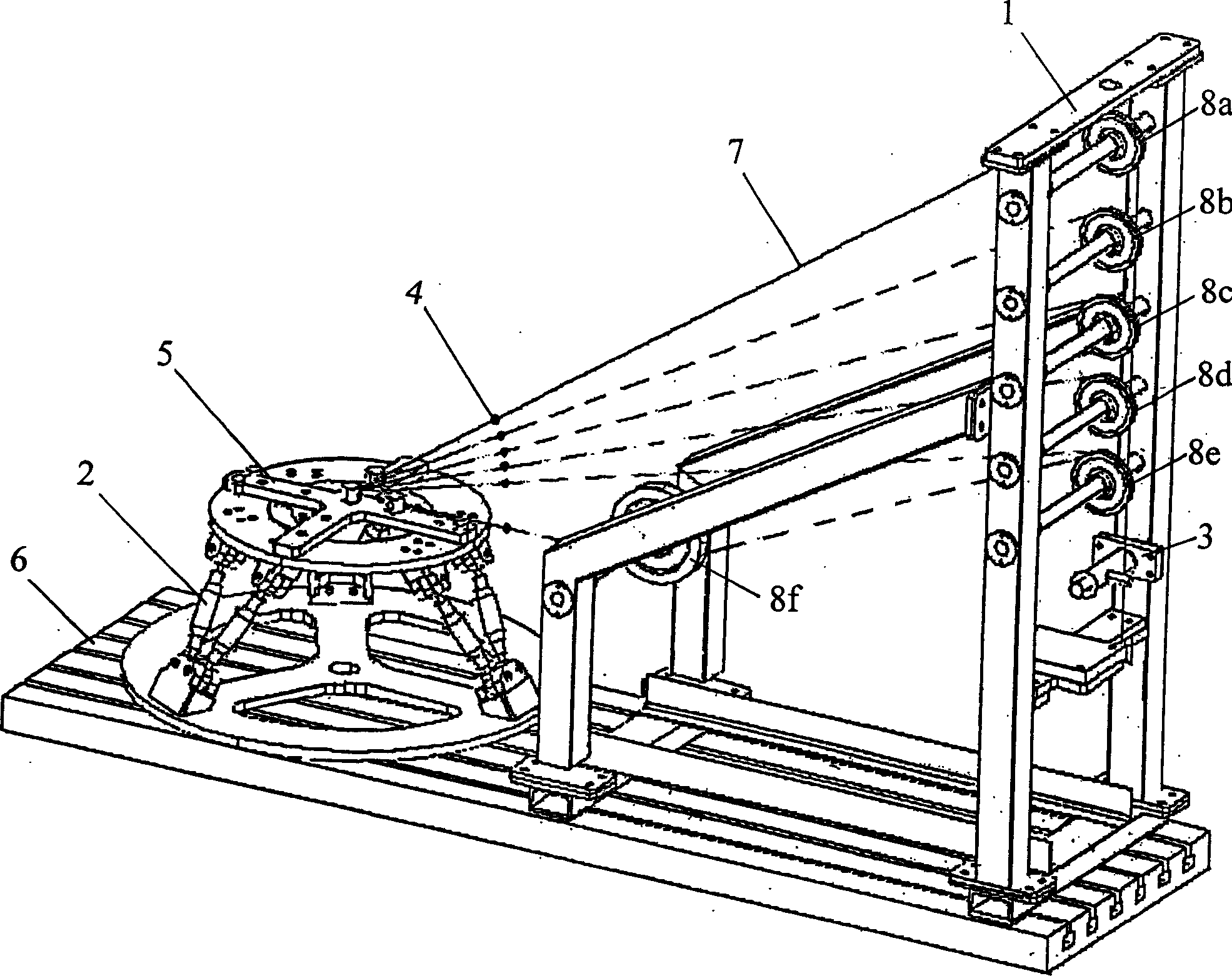
[0015] Such as figure 1 , figure 2 , image 3 As shown, the present invention includes a gantry support frame 1 composed of long and short frames, a load reducer 3, a standard one-way force sensor 4, a load coordinate cross 5, a calibration device fixed platform 6, a load transfer rope 7 and a pulley block 8; among them:
[0016] 1) The gantry support frame 1 composed of long and short frames and the six-dimensional force sensor 2 of the object to be loaded in parallel are fixed on the two end planes of the fixed platform 6 of the calibration device. The outer gantry support frame 1 is installed between the two vertical beams of the long frame. There are five pulleys 8a, 8b, 8c, 8d, 8e; the loading reducer 3 is fixed on the lower end of the pulley block 8 on the outer gantry support frame 1; the loading coordinate cross 5 is fixed to the loaded object by three bolts in parallel in six dimensions On the upper ring of the force sensor 2, and ensure that the loading coordinate cross 5 and the object to be loaded are connected in parallel, the coordinate system of the upper ring of the six-dimensional force sensor 2 is strictly consistent, and the loading point on the cross 5 is a gantry composed of long and short frames. The pulley 8f between the two vertical beams of the short frame of the supporting frame 1 is at the same level; after one end of the standard one-way force sensor 4 is connected to the load transmission rope 7, the load transmission rope 7 bypasses any pulley and then winds at the load deceleration On the rope drum 3b of the machine 3, the other end of the one-way force sensor 4 is connected to the hole on the loading coordinate cross 5 via a rope, or the other end of the one-way force sensor 4 is passed around the short frame of the inner gantry support frame 1 via a rope After the pulley 8f between the two vertical beams and the lowermost pulley 8e between the two vertical beams of the long frame of the outer gantry support frame 1, they are then wound on the rope drum 3b loaded with the reducer 3;
[0017] 2) When the load transmission rope 7 bypasses the pulley 8f on the short frame of the gantry support frame 1, ensure that the angle between the load transmission rope 7 and the horizontal plane is 0°, and the load transmission rope 7 directly bypasses the top of the gantry support frame 1 For the lower pulley 8e, ensure that the angle between the load transfer rope 7 and the horizontal plane is 15°. After that, every time the pulley that the load transfer rope 7 bypasses increases by one level, the angle between the load transfer rope 7 and the horizontal plane is increased by 5°, and the final load is obtained The angles between the transmission rope 7 and the horizontal plane are 0°, 15°, 20°, 25°, 30°, and 35°, respectively.
[0018] The loading coordinate cross 5 has two small holes equally spaced from the center hole to the four sides on each side, and the distance between the small hole and the center hole is 100 mm and 200 mm, respectively.
[0019] The load reducer 3 is a worm gear reducer, the output shaft of which is connected with a rope drum 3b.
[0020] The standard unidirectional force sensor 4 is a resistance strain sensor.
[0021] The working principle of the present invention is as follows:
[0022] The main function of the calibration device of the load object parallel six-dimensional force sensor 2 is to provide a standard generalized load, and use the standard generalized load to calibrate the static performance index of the loaded object parallel six-dimensional force sensor in all directions.
[0023] Calibrate the X-direction of the loaded object in parallel with the six-dimensional force sensor 2: Fix the loaded object in parallel with the six-dimensional force sensor 2 and the loading device on the fixed platform 6 of the calibration device, and connect the loaded object in parallel with the six-dimensional force sensor The X axis of 2 coincides with the projection of the load transfer rope 7 on the horizontal plane; the load transfer rope 7 is connected in series with the standard one-way force sensor 4, and bypasses the pulley 8f on the short side of the inner side of the gantry support frame 1, so that the load coordinate crosses After the rope from 5 to the pulley 8f is level, it goes around the pulley 8e on the outer long side of the gantry support frame 1, and then is wound on the rope drum 3b of the reducer 3. The hand wheel of the manual load reducer 3 generates an output torque through the worm gear box 3a, which is converted into the tension force K of the load transmission rope 7 through the rope drum 3b, and this tension force K acts on the object to be loaded after passing through the pulleys On the parallel six-dimensional force sensor, its size is detected by the standard unidirectional force sensor 4. Each time a force value is loaded, the output of the six tension and pressure sensors connected in parallel with the six-dimensional force sensor of the loaded object is recorded, and the loading force value is sequentially loaded 6 times from zero to full scale.
[0024] Connect the loaded object in parallel with the six-dimensional force sensor 2 and rotate it 90 degrees around its center, and turn the Y axis to the X axis direction just now, and the Y direction can be calibrated in the same way.
[0025] Calibrate the Z-direction of the parallel six-dimensional force sensor 2 of the loaded object: fix the parallel six-dimensional force sensor 2 of the loaded object and the loading device on the fixed platform 6 of the calibration device respectively, and the center of the sensor 6 is to the gantry support frame 1. The horizontal distance between the center of the pulley on the long frame measured outside is L; and the Y-axis of the parallel six-dimensional force sensor 2 of the object to be loaded coincides with the projection of the load transmission rope 7 on the horizontal plane; the load transmission rope 7 is connected in series with a standard one-way The force sensor 4 is wound on the rope drum 3b of the reducer 3 after bypassing the pulley 8a on the outer long side of the gantry support frame 1. The hand wheel of the manual load reducer 3 is loaded and calibrated, and the load acting on the parallel six-dimensional force sensor 2 of the loaded object is Fz=K*sin35°, Fy=K*cos35°. Each time a force value is loaded, the output of the six tension and pressure sensors connected in parallel with the six-dimensional force sensor of the loaded object is recorded, and the loading force value is sequentially loaded 6 times from zero to full scale. Then the load transmission rope 7 is connected in series with the standard one-way force sensor 4, and the pulleys 8b, 8c, 8d, 8e on the outer long side of the gantry support frame 1 are respectively wound around the rope drum 3b of the reducer 3. The hand wheel of the manual load reducer 3 is loaded and calibrated, and the loads acting on the parallel six-dimensional force sensor 6 of the loaded object are Fz=K*sin30°, Fy=K*cos30°; Fz=K*sin25°, Fy=K*cos25°; Fz=K*sin20°, Fy=K*cos20°; Fz=K*sin15°, Fy=K*cos15° Each time a force value is loaded, record the six-dimensional force sensor connected in parallel with the loaded object The output of a tension and pressure sensor is loaded 6 times in sequence from zero to full scale.
[0026] Perform a comprehensive calibration of the force and moment of the loaded object parallel six-dimensional force sensor 2: fix the loaded object parallel six-dimensional force sensor 2 and the loading device on the calibration device fixed platform 6, respectively, and the center of the sensor 2 to the gantry support The horizontal distance of the pulley center on the long frame measured outside of the frame 1 is L, and the X axis of the six-dimensional force sensor 6 of the parallel load object is parallel to the projection of the load transmission rope 7 on the horizontal plane; the loading coordinate crosses the load The point is offset from the center distance S along the Y axis; one end of the load transmission rope 7 is connected to the loading point, and the other end is connected in series with a standard unidirectional force sensor 4, respectively bypassing the pulleys 8a, 8b, 8c on the long side of the gantry support frame 1 , 8d, 8e are wound on the rope drum 3b of the reducer 3. The hand wheel of the manual load reducer 3 is loaded and calibrated, and the load acting on the parallel six-dimensional force sensor 6 of the loaded object is Fz=K*sin35°, Fx=K*cos35°; Fz=K*sin30°, Fy =K*cos30°; Fz=K*sin25°, Fy=K*cos25°; Fz=K*sin20°, Fy=K*cos20°; Fz=K*sin15°, Fy=K*cos15°; and torque It is Mx=Fz*S, Mz=Fx*S. Each time a force value is loaded, the output of the six tension and pressure sensors connected in parallel with the six-dimensional force sensor of the loaded object is recorded, and the loading force value is sequentially loaded 6 times from zero to full scale.
[0027]Rotate the six-dimensional force sensor 2 in parallel with the loaded object by 90 degrees around its center, and turn the Y-axis to the X-axis direction. Similarly, the six-dimensional force sensor can be connected in parallel to the loaded object with a load Fz=K*sin35°, Fy =K*cos35°; Fz=K*sin30°, Fy=K*cos30°; Fz=K*sin25°, Fy=K*cos25°; Fz=K*sin20°, Fy=K*cos20°; Fz= K*sin15°, Fy=K*cos15°; My=Fz*S, Mz=Fy*S. In the same way, record the output of the six tension and pressure sensors connected in parallel with the six-dimensional force sensor of the loaded object, and load the load force value from zero to full scale six times in sequence.
[0028] By detecting the standard 6-dimensional load F (Fx, Fy, Fz, Mx, My, Mz) and the loaded object in parallel with the six-dimensional force sensor six tension and compression sensors output force f (f1, f2, f3, f4, f5, f6 ), the calibration matrix G of the sensor can be described systematically, and they have such a relationship: G=F′·f; G: calibration matrix of the sensor; F: loaded standard six-dimensional force load; f: Six pull pressures output by the sensor. The accuracy of the calibration matrix G determines the accuracy of the sensor when measuring force. The main purpose of the present invention is to use such a device to accurately calibrate the multi-dimensional force sensor, especially the calibration matrix G of the six-dimensional force sensor connected in parallel to the loaded object.