

Apparatus for on-line coating film of float glass
A float glass and coating device technology, which is applied in the field of float glass online coating devices, can solve the problems of single function, inability to adapt and adjust, etc., and achieve the effects of simple device structure, large adjustment range and fast adjustment.
- Summary
- Abstract
- Description
- Claims
- Application Information
AI Technical Summary
Problems solved by technology
Method used
Image

Examples
Embodiment Construction
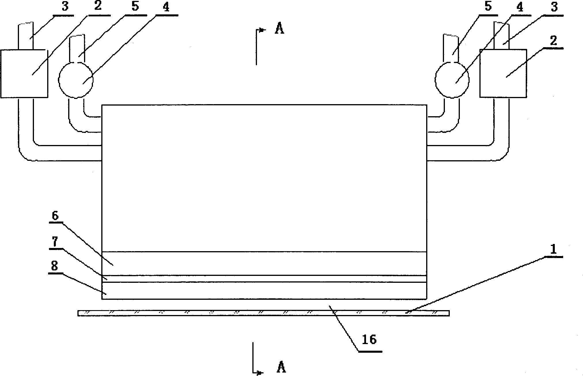
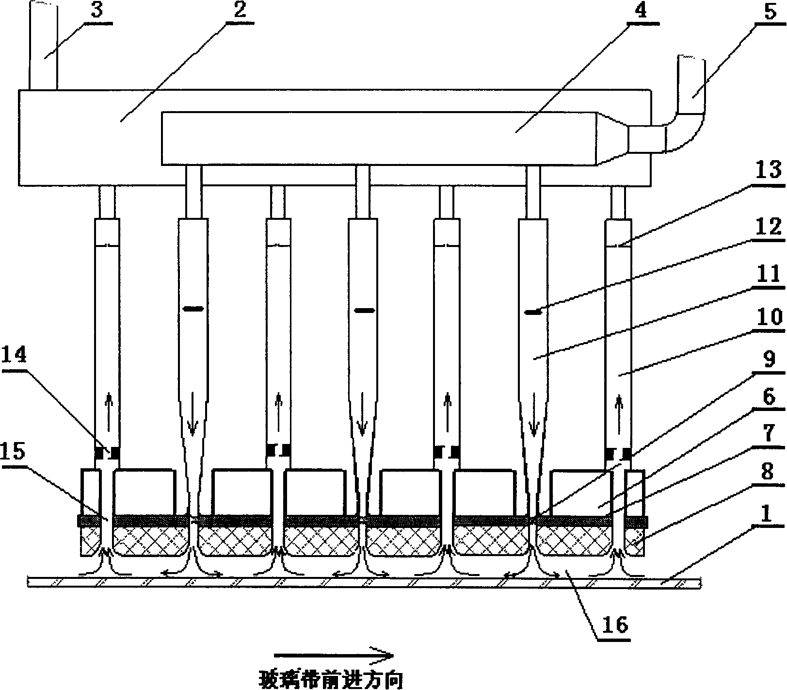
[0010] refer to figure 1 , figure 2 , the float glass on-line multifunctional coating device includes a base plate 7, the base plate 7 is composed of a plurality of strip steel plates connected, a slit 15 is left between every two steel plates, and a plurality of intake chambers alternately arranged at intervals are fixed on the base plate 7 11 and the exhaust chamber 10, the air outlet of the air inlet chamber 11 and the air inlet of the exhaust chamber 10 are respectively corresponding to the slits 15 on the bottom plate, the cooling cavity 6 is welded on the top of each bottom plate, and the graphite block 8 is fixed below , between every two graphite blocks, an air intake passage corresponding to the air intake chamber 11 and an exhaust air passage corresponding to the exhaust chamber 10 are formed. The air inlet chamber 11 is provided with an airflow damper 12, the air outlet of the air inlet chamber 11 is conical, and the exhaust chamber 10 is provided with a buffer 14...
PUM
 Abstract
Description
Claims
Application Information