[0010]In addition, because the control valve is controlled by pressure and has a structure that is not open till a certain predetermined pressure is reached, the pressure inside the piping of the cooling water circuit continuous rising till the control valve opens, and the increase in pressure inside the piping can shorten the service life of the piping of the cooling water circuit. It is an object of the present invention to enable an efficient increase in temperature of cooling water within a short period of time during the warm-up operation of an automobile and simplify the cooling device structure.
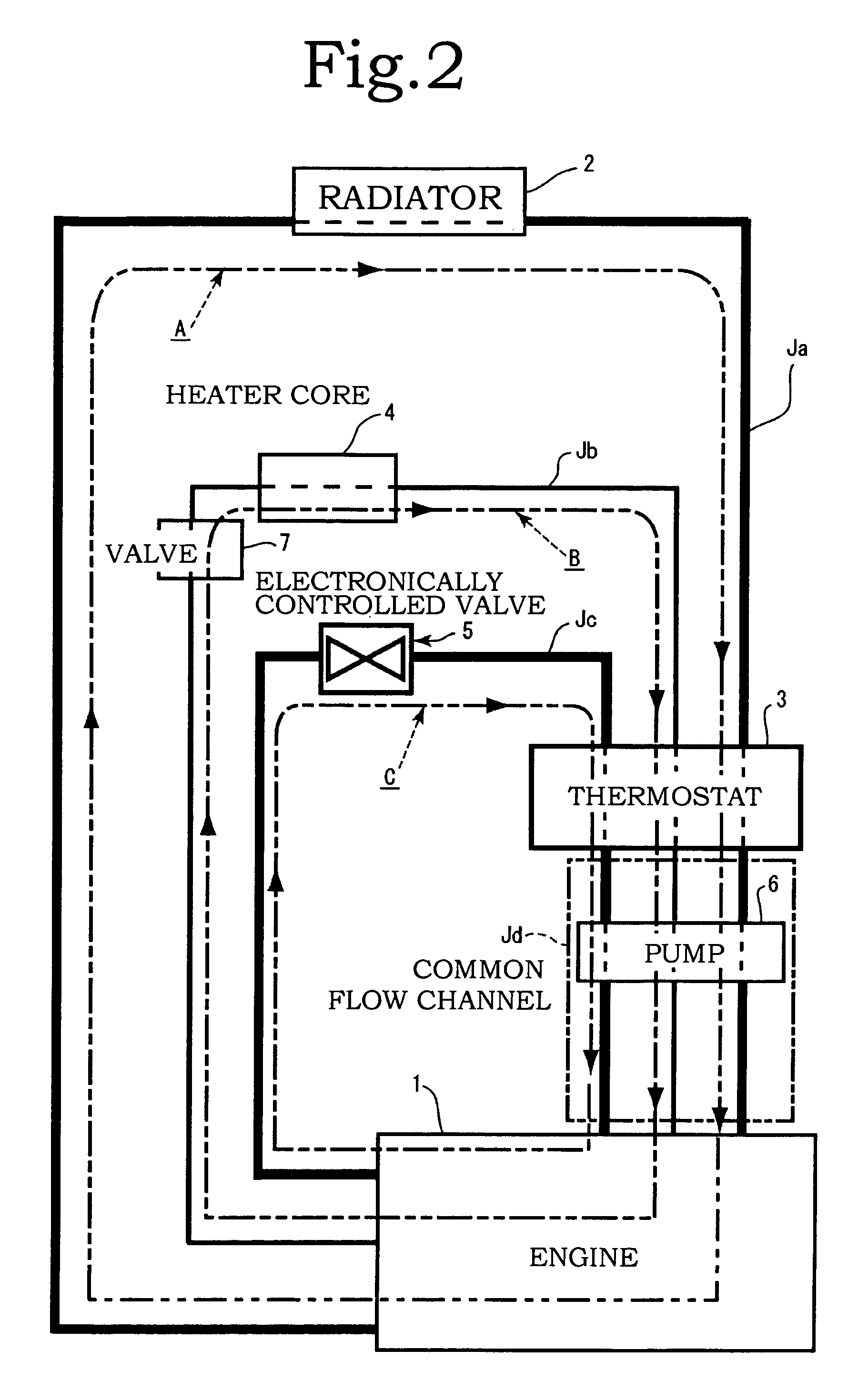
[0013]In first aspect of the invention, an electronically controlled valve is provided in which the opening degree of the opening-closing valve is gradually increased from a minimum thereof as the
cooling water temperature rises in the bypass circulation flow channel. Furthermore, at the start of the warm-up period and during the warm-up operation, the thermostat substantially stops the circulation of cooling water in the radiator circulation flow channel, and almost the entire cooling water flows through the bypass circulation flow channel. In such a state and also in a state with a low temperature of cooling water, the opening degree of the opening-closing valve of the electronically controlled valve becomes small. Therefore, the flow rate of cooling water in the location of the electronically controlled valve becomes small and the flow speed of cooling water flowing through the entire bypass circulation flow channel decreases.
[0014]As a result, an interval in which the cooling water passes inside the engine is increased and the
cooling water temperature can rise rapidly. Furthermore, at the end of the warm-up period, circulation is actuated in the radiator circulation flow channel and stopped in the bypass circulation flow channel, whereby a smooth transition can be made to the normal operation of cooling water and a smooth transition can be made from the cooling
water circulation in the bypass circulation flow channel to the cooling
water circulation in the radiator circulation flow channel.
[0015]In particular, when warming is stopped (OFF), the heater circulation flow channel is
shut down. Therefore, practically the entire cooling water flows in the bypass circulation flow channel having no
specific heat dissipation source and the cooling
water temperature can be further increased. Furthermore, because the opening and closing valve is opened and closed gradually in the electronically controlled valve and the flow of cooling water in the bypass circulation flow channel can be changed gradually, abrupt changes in the flow of cooling water inside the bypass circulation flow channel are prevented. Therefore, shock
waves can hardly occur and
noise or vibrations caused by such shock
waves can be reduced. As a result, no discomfort is caused to the driver. In addition, the service life of piping constituting the circulation flow channels can be extended.
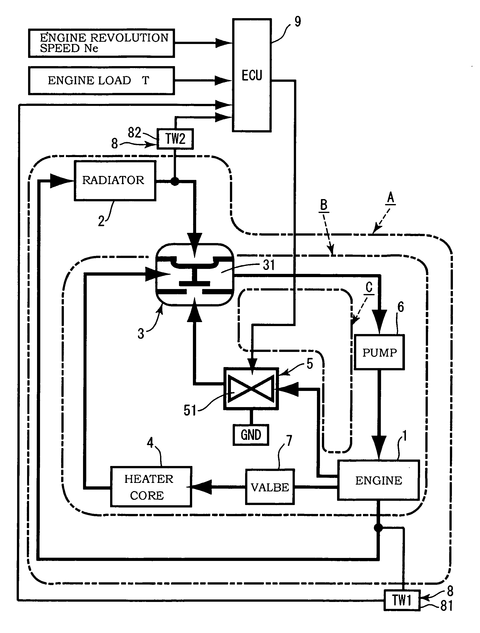
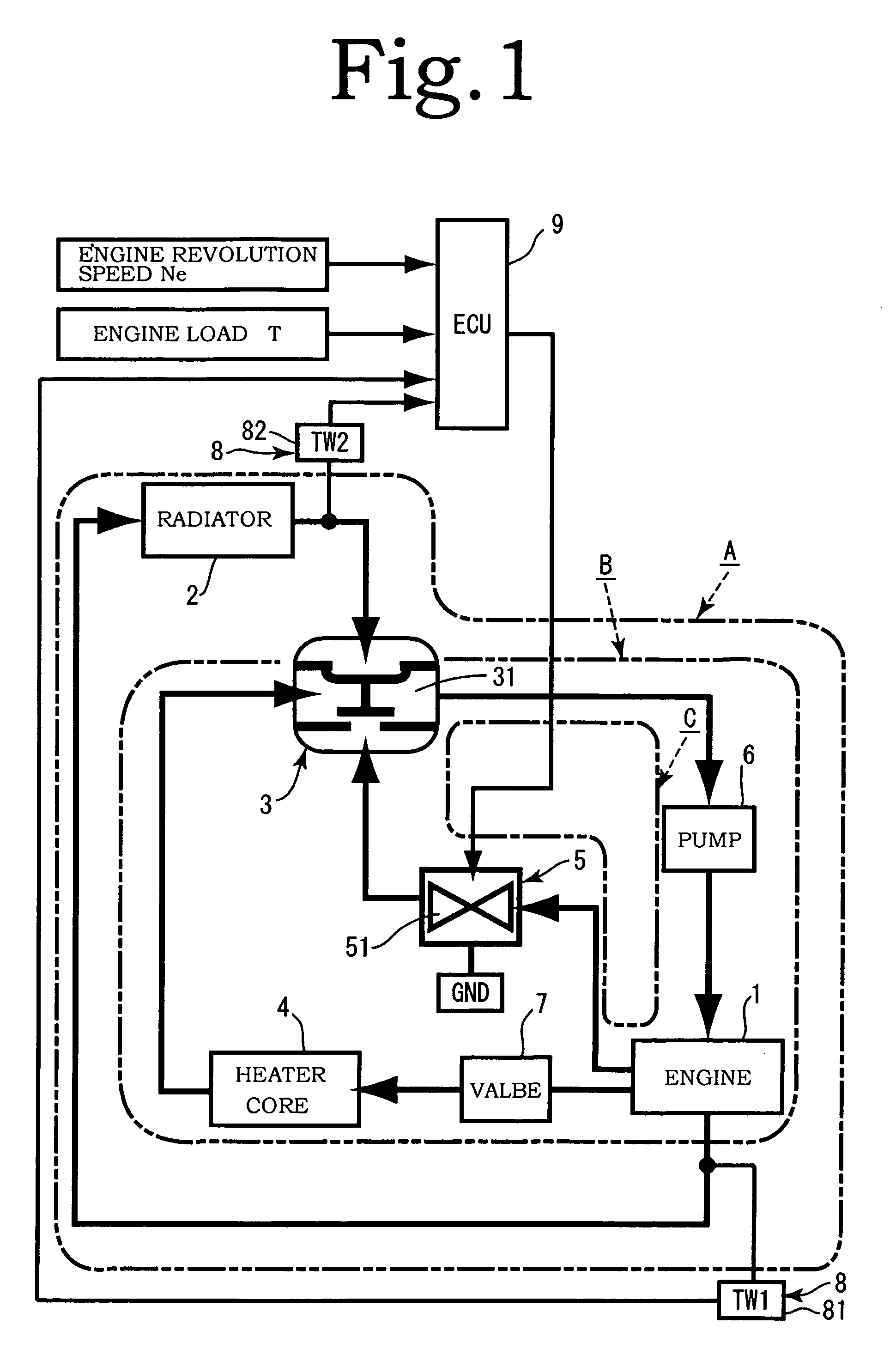
[0016]In second aspect of the invention, a
water temperature measurement and
control unit comprising a sensor and an ECU is provided in a location downstream of the engine in the radiator circulation flow channel, and a
valve opening degree of the electronically controlled valve increases gradually from a substantially
closed state with a decrease in a difference between a measured
water temperature determined by the sensor of the water
temperature measurement and
control unit and a set water temperature at the end of the warm-up period. As a result, the ECU can accurately determine the end time of the warm-up period from the temperature of cooling water, the opportunity for maximizing the opening degree of the opening-closing valve and making a transition from the cooling water circulation in the bypass circulation flow channel to the cooling water circulation in the radiator circulation flow channel can be adequately judged and realized, and very accurate transition can be made from the warm-up operation to normal operation.
[0017]In third aspect of the invention, a detection unit that detects a revolution speed of the engine and an engine load is provided, and a
valve opening degree of the electronically controlled valve gradually decreases with an increase in the engine revolution speed and load, thereby making it possible to control the flow of cooling water with the electronically controlled valve correspondingly to the temperature variations of the cooling water and also the state of the engine. In forth aspect of the invention, a heater valve is provided upstream of the
heater core of the heater circulation flow channel, and circulation in the heater circulation flow channel can be appropriately stopped. Therefore, the heater circulation flow channel can be
shut down at the start of the warm-up period and during the warm-up operation, a structure is thus obtained in which cooling water flows only in the bypass circulation flow channel, and the cooling water temperature can be rapidly raised.

