Control device based on PLC computer system

A computer system and control device technology, applied in the field of PLC control, can solve the problems of low boiler combustion efficiency, low energy utilization rate, slow stability adjustment, etc., and achieve the effects of improving work efficiency, uniform spraying, and uniform combustion

Inactive Publication Date: 2022-02-15
LUOHE VOCATIONAL TECH COLLEGE
View PDF0 Cites 0 Cited by
  • Summary
  • Abstract
  • Description
  • Claims
  • Application Information

AI Technical Summary

Problems solved by technology

[0004] In order to overcome the problems of low boiler combustion efficiency, slow stable adjustment, and low energy utilization rate, the purpose of the present invention is to provide a control device based on a PLC computer system, which has the functions of high combustion efficiency, fast temperature adjustment, and high energy utilization rate.

Method used


Image

  • Control device based on PLC computer system
  • Control device based on PLC computer system
  • Control device based on PLC computer system

Examples


Embodiment 1

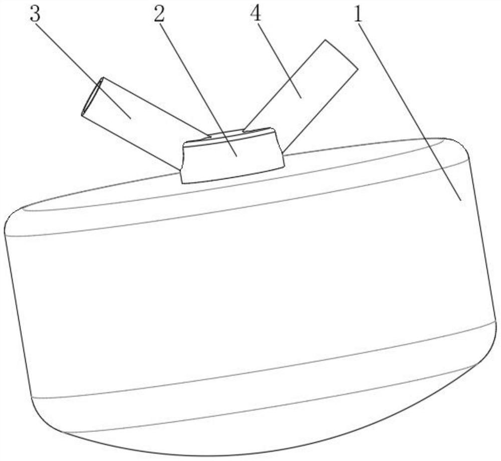
[0046] see Figure 1-3 , a control device based on a PLC computer system, comprising a furnace body 1, the top of the furnace body 1 is fixedly connected to a connecting platform 2, the top of the connecting platform 2 is interspersed with a powder material tube 3 and a block material tube 4, and the powder material tube 3 and the block material tube are interspersed. Rotate and connect the partition plate 5 in the material pipe 4;

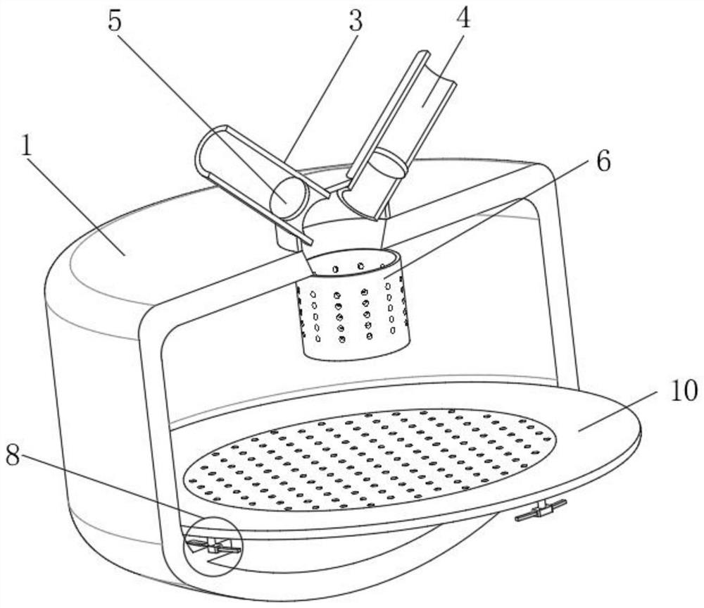
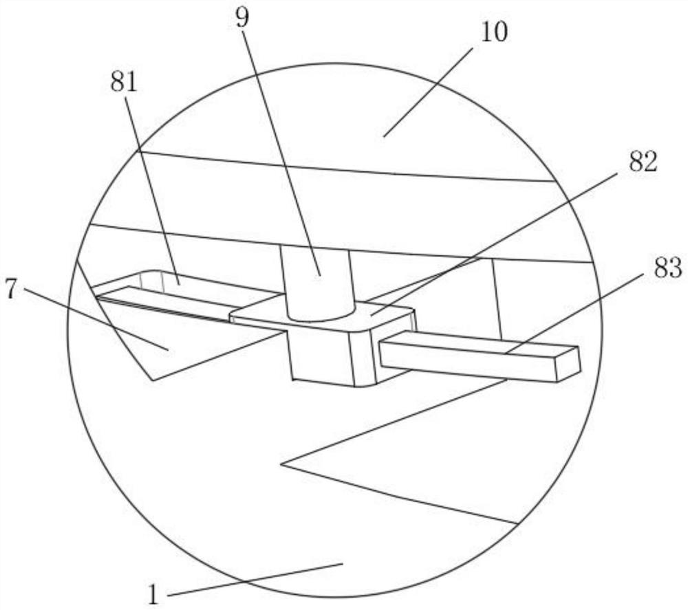
[0047] The inner wall of the furnace body 1 is fixedly connected to the base plate 7, and the top of the base plate 7 is provided with a vibrating mechanism 8 to prevent coal ash from accumulating;

[0048] A weighing device 9 is installed on the top of the vibration mechanism 8, and the top of the weighing device 9 is fixedly connected with a supporting plate 10.

[0049] The connection table 2 communicates with the discharge mechanism 6, and the inner wall of the powder material pipe 3 is provided with a fan interface, which is located on the l...

Embodiment 2

[0054] see Figure 1-6 , a control device based on a PLC computer system, comprising a furnace body 1, the top of the furnace body 1 is fixedly connected to a connection platform 2, and the top of the connection platform 2 is interspersed with a powder material tube 3 and a block material tube 4, and the powder material tube 3 and the block material tube Rotate and connect the partition plate 5 in the material pipe 4;

[0055] The inner top wall of the furnace body 1 is fixedly connected to the discharge mechanism 6 that controls the discharge method of powder and block materials;

[0056] The inner wall of the furnace body 1 is fixedly connected to the base plate 7, and the top of the base plate 7 is provided with a vibrating mechanism 8 to prevent coal ash from accumulating;

[0057] A weighing device 9 is installed on the top of the vibration mechanism 8, and the top of the weighing device 9 is fixedly connected with a supporting plate 10.

[0058] The connection table 2 ...

Embodiment 3

[0068] see Figure 7-8 , a method for using a control device based on a PLC computer system, the steps comprising:

[0069] S1. Select or write the required PLC program according to the usage, and input it into the PLC control system, turn on the equipment, start the PLC control, and control the operation of the equipment according to the PLC system settings;

[0070] S2. The system controls the material control device to throw fuel to the powder supply device and the lump supply device. The lump supply device releases the lump first, the igniter is ignited, and the powder supply device throws powder to support combustion;

[0071] S3. The equipment operates according to the system settings. When the fuel is burned, the oscillating device controls the incineration platform to shake, so that the coal ash falls;

[0072] S4. The temperature measurement module detects the temperature in the furnace. When the temperature is lower than the set temperature, enter step S8. When the ...


PUM


Abstract

The invention discloses a control device based on a PLC computer system, which comprises a furnace body, the top of the furnace body is fixedly connected with a connecting table, a powder material pipe and a block material pipe are arranged at the top of the connecting table in a penetrating mode, and a partition plate is rotationally connected in the powder material pipe and the block material pipe; the inner top wall of the furnace body is fixedly connected with a discharging mechanism for controlling the discharging method of powder and lump materials; and the inner wall of the furnace body is fixedly connected with a bottom plate, and the top of the bottom plate is provided with a vibration mechanism for preventing coal ash accumulation. According to the control device based on the PLC computer system, coal fuels in two different states are fed according to work, when the temperature is insufficient, whether coal lacks or not is determined firstly, if coal lacks, a partition plate in a lump material pipe is turned over, a channel is opened, and lump materials fall into a furnace body, and after the lump materials are fed, a partition plate in a powder material pipe is turned over, the channel is opened, the powder is carried by the air flow generated by a fan to be sprayed into the furnace body to support the combustion of the block materials, and the temperature in the furnace can be quickly increased, so that the working efficiency is improved.

Description

technical field [0001] The invention relates to the technical field of PLC control, in particular to a control device based on a PLC computer system. Background technique [0002] The full name of PLC is programmable logic controller, which is an electronic device specially designed for industrial production. It uses a type of programmable memory for its internal storage program, logic operation, sequence control, timing , Counting and arithmetic operations and other user-oriented instructions, and control various types of machinery or production processes through digital or analog input / output, are the core parts of industrial control. [0003] Industrial boilers are equipment used to provide power, heat, and hot water in industrial production. Due to the simple feeding method of boilers at present, the combustion efficiency of boilers is low, the temperature adjustment is slow, and the energy utilization rate is low. Therefore, we propose a PLC-based computer system contr...

Claims


Application Information

Patent Timeline
Patent Type & Authority Applications(China)
IPC IPC(8): F23K3/02F23K3/22F23N1/02F23N5/02
CPCF23K3/02F23K3/22F23N1/025F23N5/02
Inventor 冯若愚杨洋吴丹冯凯陈桂华
Owner LUOHE VOCATIONAL TECH COLLEGE
Why Eureka
Try Eureka