Magnetic thermal reactor device

A reactor, magnetocaloric technology, applied in chemical instruments and methods, chemical/physical/physical-chemical processes, chemical/physical/physical-chemical processes using energy, etc. Meet environmental protection requirements, slow heating speed and other problems, to achieve the effect of meeting large-scale industrial production, high energy efficiency, and rapid temperature rise

Active Publication Date: 2016-09-21
NANUS NEW MATERIAL
View PDF4 Cites 1 Cited by
  • Summary
  • Abstract
  • Description
  • Claims
  • Application Information

AI Technical Summary

Problems solved by technology

[0004] The purpose of the present invention is to provide a magnetocaloric reactor device in order to improve the deficiencies of the prior art, apply the magnetocaloric reaction to the reactor, and use the magnetocaloric effect to heat the reaction; mainly to solve the problems existing in the traditional reactor Disadvantages such as low efficiency, high cost, slow heating speed, and failure to meet environmental protection requirements
At the same time, expand the application field of magnetocaloric reaction, and solve the problems of difficult temperature control in the application of magnetocaloric reaction in the reactor field, and there are no cooling devices and inert gas protection devices.

Method used


Image

  • Magnetic thermal reactor device

Examples


Embodiment 1

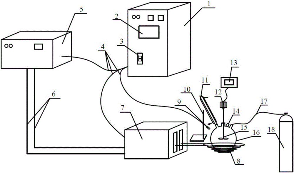
[0016] The magnetocaloric reactor device of the present invention that utilizes the magnetocaloric effect to heat the reaction is mainly composed of: a magnetocaloric power supply 1, a cooling system 5, a magnetocaloric transformer 7, a magnetocaloric coil 8 and a reactor 16. Among them, the magnetocaloric power supply 1 has a first control panel 2 and a power switch 3; the reactor 16 includes an infrared temperature measuring device 9, a condensation device 11, a material inlet 14, a stirring device 15, and an inert gas tank 18. The reactor 16 has four openings, of which the left opening is connected to the condensing device 11, the middle opening is connected to the stirring device 15, the right opening is connected to the air duct 17, and the side front opening is the material inlet 14. The cooling system 5 and the magnetocaloric transformer 7 are connected to the magnetocaloric power supply through a power line 4, the cooling system 5 and the magnetocaloric transformer 7 are...

Embodiment 2

[0020] The device is as described in Example 1. Take 3.8437g of anhydrous citric acid and 2.3833g of L-threonine, add 0.6339g (mass fraction 10%) of ferroferric oxide with a particle size of 20nm, stir and mix evenly, turn on the inert gas Switch and let in nitrogen gas. Turn on the magnetocaloric power switch, set the constant power program operation mode, set the power range to 12KW, and run time to 100 seconds. Press the reaction switch and the reaction will proceed. After the reaction is over, the taken-out solid is dissolved in water, and the magnetic medium is sucked out with a magnet, and the supernatant is the synthesized fluorescent carbon nanoparticle solution. Compared with other preparations of carbon nanoparticles, this method has the advantages that the heating speed is fast, and fluorescent nanomaterials can be synthesized in 100 seconds; we have obtained 4.5333g carbon dot solid powder, which can be used to prepare fluorescent materials on a large scale; The y...

Embodiment 3

[0022] The device is as described in Example 1. Hydroxypropyl acrylate (HPA), vinyl pyrrolidone (NVP), methylene bisacrylamide (MBAA), redox agent combination ammonium persulfate (APS) is miscible in glycerin, Stir uniformly in the reactor, and then add tetramethylethylenediamine (TMEDA). The relationship between the components is: HPA / NVP=3:1wt / wt(3g:1g), glycerin 6g, APS=0.4wt%(0.04g), [APS] / [TMEDA]=1:4mol / mol, MBAA =0.01wt% (0.001g). Then, 0.2 g (mass fraction 20%) of 50nm ferroferric oxide was added to the reactor, and the mixture was stirred and mixed uniformly. Turn on the magnetocaloric power switch, set the constant power operation mode, set the set power to 14KW, press the switch, about 30 seconds can provide enough energy to excite the magnetic particles to vibrate to generate heat, thereby preparing the hydrogel material. The use of magnetocaloric effect to initiate front-end polymerization is a new front-end polymerization method; at the same time, the prepared hy...


PUM


Abstract

The invention relates to a magnetic thermal reactor device which is formed by a magnetic heat power source (1), a cooling system (5), a magnetic heat transformer (7), a magnetic heat coil (8) and a reactor (16), wherein the reactor (16) has four openings, the opening at the left upper part is connected with a condensing unit (11), and a stirring device (15) in the reactor is connected with a rotating motor (12) by the opening in the top of the middle; the opening in the right upper part is connected with an inert gas tank (18) after being connected with an air duct (17), a material inlet (14) is arranged at the lateral front part, and an infrared temperature measuring device (9) is fixed on an iron stand (10) above the left side of the reactor (16), right faces to a reactant in the reactor (16), and is connected with the magnetic heat power source by a power line (4); the reactor (16) is fixed on the magnetic heat coil (8), and the magnetic heat coil (8) is fixed on the magnetic heat transformer (7) by a screw; and the cooling system (5) and the magnetic heat transformer (7) are connected with the magnetic heat power source (1) respectively by the power line (4), and the cooling system (5) is connected with the magnetic heat transformer (7) by a cooling water pipe (6). The magnetic thermal reactor device can solve the defects of low efficiency, high cost, low heating speed and incapability of meeting the requirement of environmental protection in conventional reactors.

Description

Technical field [0001] The invention relates to a magnetocaloric reactor device, more specifically a reactor device that uses the magnetocaloric effect to heat the reaction. Background technique [0002] The reactor is the equipment to realize the reaction process, which is widely used in chemical industry, oil refining, metallurgy, light industry and other industrial sectors. At present, most of the reactors used by production enterprises and scientific research units in various countries use gas, coking coal, oil furnace, electric furnace and other gas combustion heating and electric heating methods. This heat can only be transferred to by means of heat transfer (heat conduction, heat convection, heat radiation) The object that needs to be heated can achieve the purpose of heating the reactant. Because of these heating methods, the heated object is heated by absorbing external heat. Therefore, they are all indirect heating methods. We know that the natural heat transfer law ...

Claims


Application Information

Patent Timeline
Patent Type & Authority Applications(China)
IPC IPC(8): B01J19/08
CPCB01J19/087B01J2219/00123B01J2219/00139
Inventor 陈苏沈军才佘兴金于超
Owner NANUS NEW MATERIAL
Why Eureka
Try Eureka