Excavator energy-recuperation system

An energy recovery and excavator technology, which is applied in the direction of mechanically driven excavators/dredgers, etc., can solve the problems of heavy weight of hydraulic excavators, shortened life of hydraulic components, and increased system temperature, so as to improve energy utilization. , prolong life, reduce the effect of throttling energy loss

Inactive Publication Date: 2010-02-24
四川升腾元创机电技术研究有限公司
View PDF0 Cites 43 Cited by
  • Summary
  • Abstract
  • Description
  • Claims
  • Application Information

AI Technical Summary

Problems solved by technology

[0002] During the working process of the hydraulic excavator, the boom swings up and down frequently, and the working device of the hydraulic excavator is heavy and has a large inertia. However, when decelerating and braking, most of the potential energy of the working device is converted into heat energy at the main valve orifice, which not only causes energy waste, but also leads to a rise in system temperature and a reduction in the life of hydraulic components.

Method used


Image

  • Excavator energy-recuperation system
  • Excavator energy-recuperation system

Examples


Embodiment 1

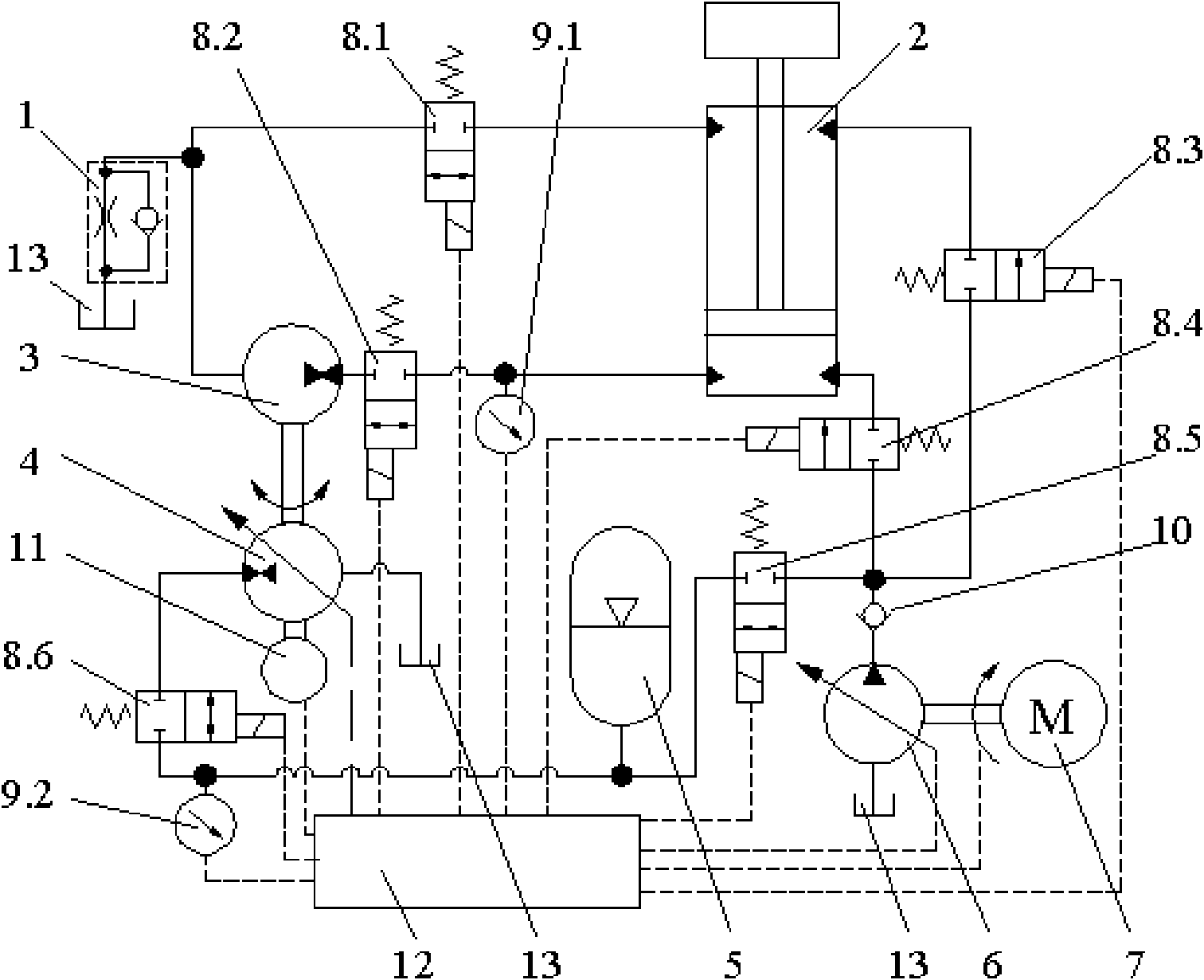
[0014] see figure 1 , This embodiment includes a hydraulic cylinder 2, an oil tank 13, a quantitative pump / motor 3, a valve and an engine 7. The key technology is to install the first variable pump / motor 4 and the speed measuring photoelectric encoder 11 coaxially with the quantitative pump / motor 3, the quantitative pump / motor 3 and the first variable pump / motor 4 form a hydraulic transformer; one end of the quantitative pump / motor 3 The second reversing valve 8.2 is connected with the lower chamber of the hydraulic cylinder 2, and the second reversing valve 8.2 is also connected with the first pressure sensor 9.1; Oil tank 13, the other way is connected with the upper cavity of hydraulic cylinder 2 through the first reversing valve 8.1, and the one-way throttle valve 1 is used to increase the fluid pressure returned to the oil tank 13 output by the quantitative pump / motor 3, so that the fluid pressure returned to the oil tank 13 Part of the fluid is supplied back to hydrauli...

Embodiment 2

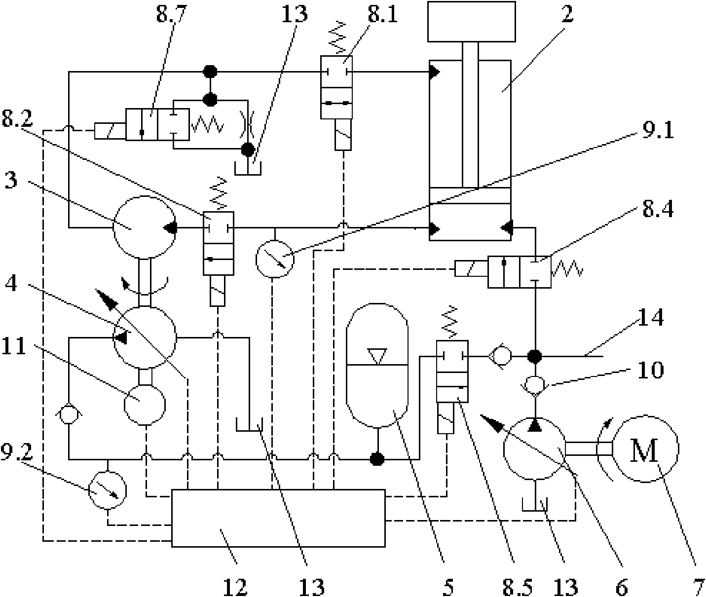
[0016] see figure 2 , This embodiment includes a hydraulic cylinder 2, an oil tank 13, a quantitative pump / motor 3, a valve and an engine 7. The key technology is to install the first variable pump / motor 4 and the speed measuring photoelectric encoder 11 coaxially with the quantitative pump / motor 3, the quantitative pump / motor 3 and the first variable pump / motor 4 form a hydraulic transformer; one end of the quantitative pump / motor 3 The second reversing valve 8.2 is connected to the lower chamber of the hydraulic cylinder 2, and the second reversing valve 8.2 is also connected to the first pressure sensor 9.1; the other end of the quantitative pump is divided into two circuits, and the first one is connected through the seventh reversing valve 8.7 Oil tank 13, the other way is connected with the upper chamber of hydraulic cylinder 2 through the first reversing valve 8.1, and the seventh reversing valve 8.7 is used to increase the fluid pressure returned to the oil tank 13 ou...


PUM


Abstract

An excavator energy-recuperation system relates to an excavator moving arm energy saving system, comprising a hydraulic cylinder, a fuel tank, a quantitative pump, a valve and an engine. The key technology is that a first variable pump and a speed determining photoelectric encoder are coaxial equipped with the quantitative pump. One end of the quantitative pump is connected with a hydraulic cylinder through a reversing valve and the other end of the quantitative pump is respectively connected with the fuel tank and the hydraulic cylinder on two branches. One end of the first variable pump is connected with the fuel tank and the other end is connected with an accumulator through the reversing valve. A second variable pump is coaxial arranged with the engine, one end of the second variable pump is connected with the fuel tank and and the other end is connected with a check valve; a fuel outlet of the check valve has three branches, wherein the first one is connected with the accumulatorthrough the reversing valve; the second one is connected with a hydraulic cylinder through the reversing valve; and the third one is connected with a hydraulic cylinder through the reversing valve. The invention combines the flow regeneration and potential energy recuperation, thus simultaneously realizing the flow regeneration and the energy-recuperation recycling, improving the utilization rateof the excavator energy and prolonging the service life of the excavator.

Description

Technical field: [0001] An energy recovery system for an excavator relates to an energy-saving system for an excavator arm. Background technique: [0002] During the working process of the hydraulic excavator, the boom swings up and down frequently, and the working device of the hydraulic excavator is heavy and has a large inertia. However, during deceleration and braking, a large amount of potential energy of the working device is mostly converted into heat energy at the main valve orifice, which not only causes energy waste, but also leads to an increase in system temperature and a reduction in the life of hydraulic components. Invention content: [0003] The problem to be solved by the present invention is to provide a novel boom energy-saving system that combines flow regeneration and potential energy recovery, which can simultaneously realize flow regeneration and energy recovery and reuse, and improve the utilization rate of excavator energy. , Extend the life of th...

Claims


Application Information

Patent Timeline
Patent Type & Authority Applications(China)
IPC IPC(8): E02F3/42
Inventor 刘桓龙柯坚张树忠王国志于兰英邓斌吴文海邓迎宾
Owner 四川升腾元创机电技术研究有限公司
Why Eureka
Try Eureka