Excavator energy-recuperation system
An energy recovery and excavator technology, which is applied in the direction of mechanically driven excavators/dredgers, etc., can solve the problems of heavy hydraulic excavator working equipment, reduced life of hydraulic components, and rise in system temperature, so as to improve energy utilization. , prolong life, reduce the effect of throttling energy loss
- Summary
- Abstract
- Description
- Claims
- Application Information
AI Technical Summary
Problems solved by technology
Method used
Image
Examples
Embodiment 1
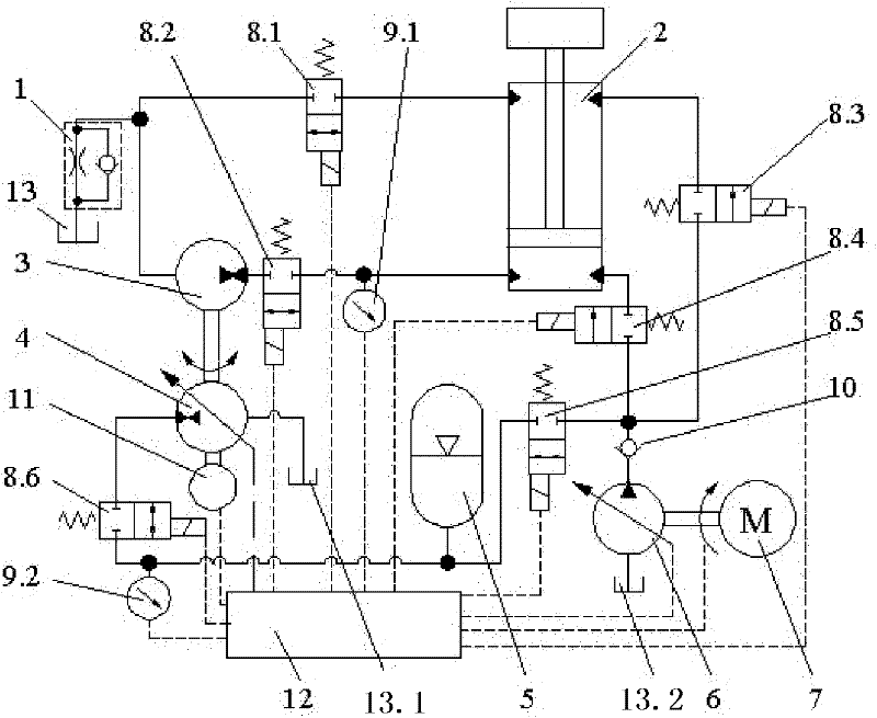
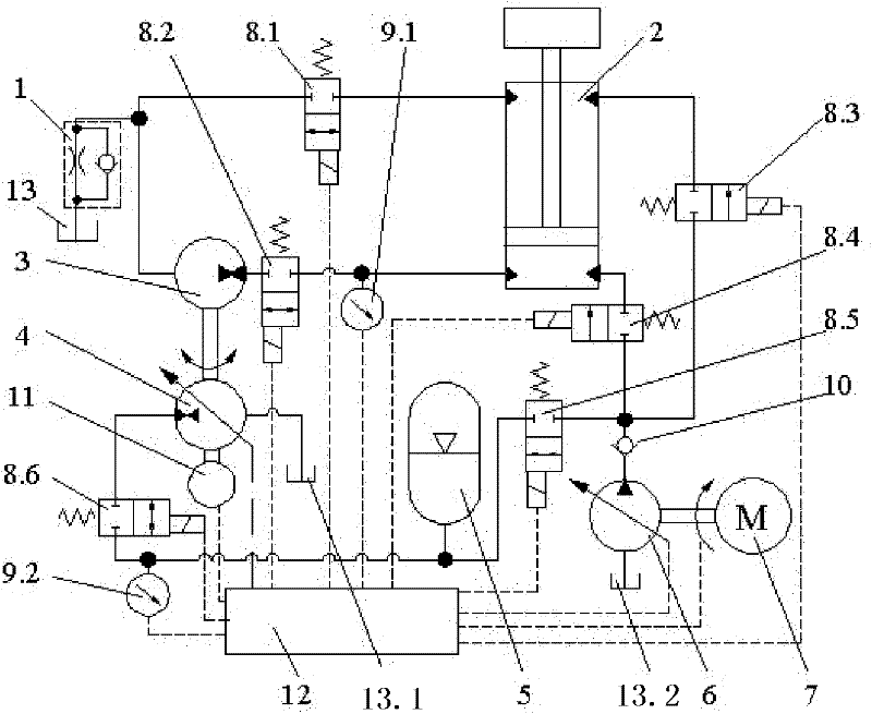
[0014] see figure 1 , This embodiment includes a hydraulic cylinder 2, an oil tank 13, a quantitative pump / motor 3, a valve and an engine 7. The key technology is to install the first variable pump / motor 4 and the speed measuring photoelectric encoder 11 coaxially with the quantitative pump / motor 3, the quantitative pump / motor 3 and the first variable pump / motor 4 form a hydraulic transformer; one end of the quantitative pump / motor 3 The second reversing valve 8.2 is connected with the lower chamber of the hydraulic cylinder 2, and the second reversing valve 8.2 is also connected with the first pressure sensor 9.1; The first oil tank 13, the other way is connected with the upper chamber of the hydraulic cylinder 2 through the first reversing valve 8.1, and the one-way throttle valve 1 is used to increase the fluid pressure output by the quantitative pump / motor 3 and return to the first oil tank 13, so that A part of the fluid returned to the first oil tank 13 is supplied back...
Embodiment 2
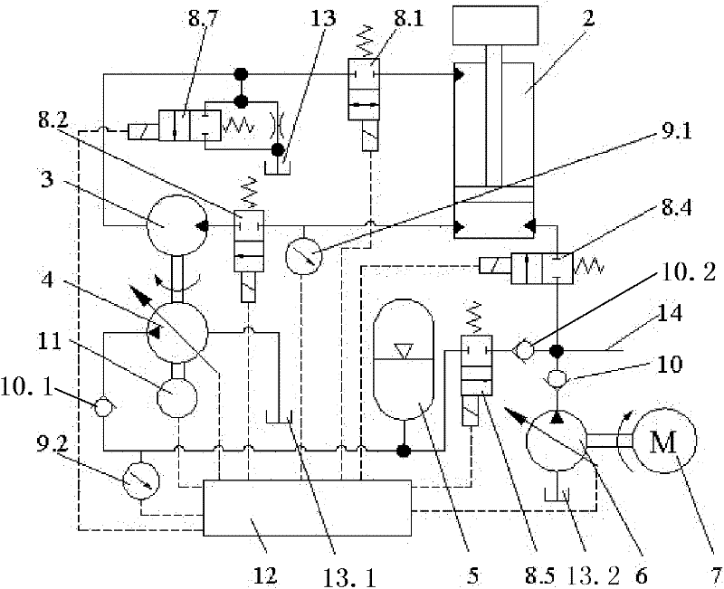
[0016] see figure 2 , This embodiment includes a hydraulic cylinder 2, an oil tank 13, a quantitative pump / motor 3, a valve and an engine 7. The key technology is to install the first variable pump / motor 4 and the speed measuring photoelectric encoder 11 coaxially with the quantitative pump / motor 3, the quantitative pump / motor 3 and the first variable pump / motor 4 form a hydraulic transformer; one end of the quantitative pump / motor 3 The second reversing valve 8.2 is connected to the lower chamber of the hydraulic cylinder 2, and the second reversing valve 8.2 is also connected to the first pressure sensor 9.1; the other end of the quantitative pump is divided into two circuits, and the first one is connected through the seventh reversing valve 8.7 The first oil tank 13, the other way is connected with the upper cavity of the hydraulic cylinder 2 through the first reversing valve 8.1, and the seventh reversing valve 8.7 is used to increase the fluid pressure output by the qua...
PUM
 Abstract
Description
Claims
Application Information
 - R&D
- Intellectual Property
- Life Sciences
- Materials
- Tech Scout
- Unparalleled Data Quality
- Higher Quality Content
- 60% Fewer Hallucinations
Browse by: Latest US Patents, China's latest patents, Technical Efficacy Thesaurus, Application Domain, Technology Topic, Popular Technical Reports.
© 2025 PatSnap. All rights reserved.Legal|Privacy policy|Modern Slavery Act Transparency Statement|Sitemap|About US| Contact US: help@patsnap.com


