High-pressure large-flow oil cylinder regeneration hydraulic system of excavator

A hydraulic system and large flow technology, which is applied in the direction of fluid pressure actuation system components, mechanical equipment, fluid pressure actuation devices, etc., can solve the problems of low efficiency of the hydraulic system, suction of the hydraulic system, damage to hydraulic components, etc. Reliability, reduced energy consumption, and increased motion speed

Pending Publication Date: 2021-11-23
XUZHOU XCMG MINING MACHINERY CO LTD
View PDF0 Cites 0 Cited by
  • Summary
  • Abstract
  • Description
  • Claims
  • Application Information

AI Technical Summary

Problems solved by technology

[0002] The working device of a super-large hydraulic excavator has a large mass. When the boom is lowered or the stick is retracted, the boom and the stick will fall by themselves due to their own weight. The back pressure is used to balance the gravity of the structural parts. At this time, the pressure on the oil supply side of the cylinder is very low, and the outlet flow of the main pump only meets the oil supply side of the cylinder without suction, and the oil return side of the cylinder returns to the hydraulic oil tank through throttling. A large amount of heat is dissipated through the heat dissipation system, which will lead to low efficiency of the hydraulic system of the super large hydraulic excavator; at the same time, in order to meet the requirements of the compound action of the working device, the flow required by the oil supply side of the oil cylinder is greater than the flow provided by the main pump, which will cause the oil cylinder supply. Insufficient flow on the oil side will lead to cavitation in the hydraulic system, and the air bubbles will damage the hydraulic components and reduce the reliability of the ultra-large hydraulic excavator

Method used


Image

  • High-pressure large-flow oil cylinder regeneration hydraulic system of excavator

Examples


Embodiment Construction

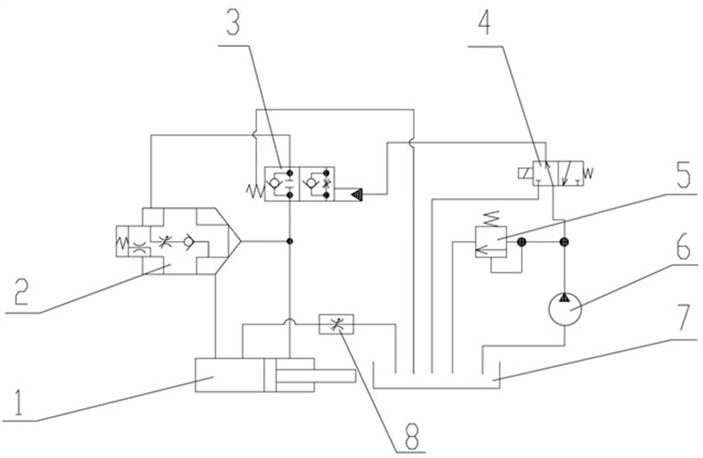
[0014] Such as figure 1 The high-pressure and large-flow hydraulic cylinder regenerative hydraulic system of the excavator includes a hydraulic cylinder 1, a cartridge valve 2 is provided between the large chamber and the small chamber of the hydraulic cylinder 1, and the cartridge valve 2 is connected with a hydraulic control reversing Valve 3, the hydraulic control reversing valve 3 is controlled by the electromagnetic reversing valve 4, the electromagnetic reversing valve 4 is connected with the hydraulic oil tank 7 through the pilot relief valve 5 and the gear pump 6, the large A throttle valve 8 is provided between the cavity and the hydraulic oil tank 7, and a controller for controlling the electromagnetic reversing valve 4 is also included. The pilot overflow valve 5 arranged between the electromagnetic reversing valve 4 and the hydraulic oil tank 7 controls the system pressure at 3.9Mpa. The controller participates in controlling the extension and contraction of the g...


PUM


Abstract

The invention discloses a high-pressure large-flow oil cylinder regeneration hydraulic system of an excavator. The system comprises a hydraulic oil cylinder, wherein a cartridge valve is arranged between a large cavity and a small cavity of the hydraulic oil cylinder and connected with a hydraulic control reversing valve; the hydraulic control reversing valve is controlled through a solenoid operated directional valve; the solenoid operated directional valve is connected with a hydraulic oil tank through a pilot overflow valve and a gear pump; a throttle valve is arranged between the large cavity of the hydraulic oil cylinder and the hydraulic oil tank; and the system further comprises a controller for controlling the solenoid operated directional valve. According to the high-pressure large-flow oil cylinder regeneration hydraulic system of the excavator, the cartridge valve and the hydraulic control reversing valve are combined, the solenoid operated directional valve controls reversing of the hydraulic control reversing valve, so that opening and closing of the cartridge valve are controlled, and when the cartridge valve is closed, the large cavity and the small cavity of the hydraulic oil cylinder work independently and do not interfere with each other; and when the cartridge valve is opened, the large cavity and the small cavity of the hydraulic oil cylinder are communicated, the hydraulic oil regeneration function of the hydraulic oil cylinder is achieved, the speed of action of the hydraulic oil cylinder is increased, engine energy consumption is reduced, and overall reliability is improved.

Description

technical field [0001] The invention relates to the technical field of engineering machinery transmission systems, in particular to a high-pressure and large-flow oil cylinder regenerative hydraulic system for excavators. Background technique [0002] The working device of a super-large hydraulic excavator has a large mass. When the boom is lowered or the stick is retracted, the boom and the stick will fall by themselves due to their own weight. The back pressure is used to balance the gravity of the structural parts. At this time, the pressure on the oil supply side of the cylinder is very low, and the outlet flow of the main pump only meets the oil supply side of the cylinder without suction, and the oil return side of the cylinder returns to the hydraulic oil tank through throttling. A large amount of heat is dissipated through the heat dissipation system, which will lead to low efficiency of the hydraulic system of the super large hydraulic excavator; at the same time, i...

Claims


Application Information

Patent Timeline
Patent Type & Authority Applications(China)
IPC IPC(8): F15B15/14F15B13/02F15B21/14
CPCF15B15/14F15B13/02F15B21/14F15B2013/004F15B2211/88
Inventor 石立京王勇夏书强李寿鹏吕建森周显孙文庆刘松阳周开坤
Owner XUZHOU XCMG MINING MACHINERY CO LTD
Why Eureka
Try Eureka