
Fast responding control device of turbine leaf apex gap control system based on shape memory alloy

A technology of memory alloy and control system, which is applied in the direction of leakage prevention, engine components, machines/engines, etc. It can solve the problems of strain characteristics (unstable direction and size, weak theory and technology, complex structure, etc.) to improve engine turbine efficiency , fast action speed and high control precision

Active Publication Date: 2015-01-28
南京长江工业技术研究院有限公司
View PDF6 Cites 19 Cited by
  • Summary
  • Abstract
  • Description
  • Claims
  • Application Information

AI Technical Summary

Problems solved by technology

However, because the strain characteristics (direction and size) of the piezoelectric crystal, the core component of the device’s operation, are unstable under the action of an electric field, further research is required to match the blade tip clearance requirements of the engine in various states. At the same time, the device needs to be energized, increasing The circuit control system has a complex structure, which requires high processing and equipment precision in the small space outside the turbine case.
[0010] At present, there is no mechanical active control system applied in engineering practice in China. The theory and technology of mechanical control are relatively weak, and further research is needed.

Method used


Image

  • Fast responding control device of turbine leaf apex gap control system based on shape memory alloy
  • Fast responding control device of turbine leaf apex gap control system based on shape memory alloy
  • Fast responding control device of turbine leaf apex gap control system based on shape memory alloy

Examples


Embodiment Construction

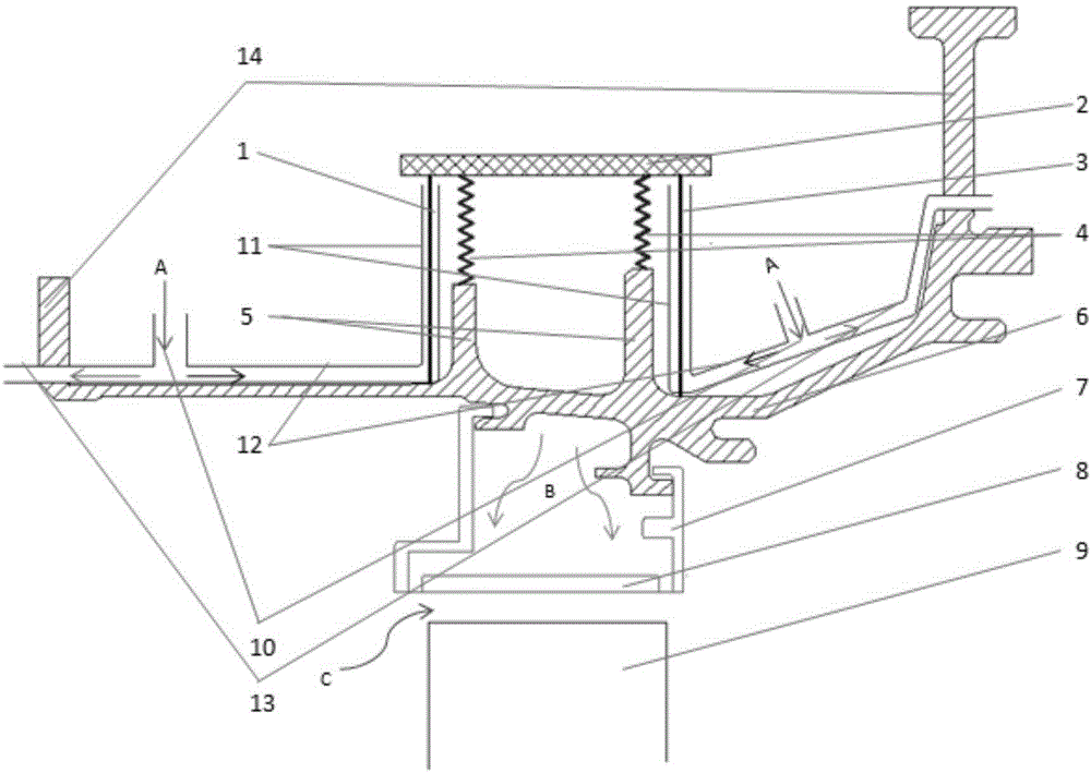
[0030] Please refer to figure 1 As shown, the present invention is based on the quick response control device of the memory alloy turbine blade tip clearance control system, acting on the casing 6, which includes a memory alloy drive system and a vortex tube cooling system, and the memory alloy drive system includes a first memory alloy wire 1. The second memory alloy wire 3 arranged in parallel with the first memory alloy wire 1, the movable plate 2 and the bias spring 4, the vortex tube cooling system includes the vortex tube 10 installed on the casing 6, the cold end of the vortex tube Cooling pipeline 11, vortex tube cold end outlet pipeline 12 and vortex tube hot end outlet pipeline 13, vortex tube 10 includes two spaced apart ones installed on the casing 6, vortex tube 10 and vortex tube cold end The cooling pipelines 11 are connected through the outlet pipeline 12 at the cold end of the vortex tube. The outlet pipeline 12 at the cold end of the vortex tube and the outle...


PUM


Abstract

The invention discloses a fast responding control device of a turbine leaf apex gap control system based on a shape memory alloy (SMA). The fast responding control device of the turbine leaf apex gap control system based on the SMA comprises an SMA driving system and a vortex tube cooling system, wherein the SMA driving system comprises an SMA wire, a biasing spring and a movable board, the vortex tube cooling system comprises a vortex tube and a vortex tube cooling end cooling pipeline, one end of the SMA wire is fixed on a vortex tube cooling end outlet pipeline, the other end of the SMA wire is connected to the movable board, and the two ends of biasing spring are respectively connected to a power brake reinforcing rib and the movable board. The excellent memory recovering performance of the SMA under different temperature conditions and the immediate refrigeration and heating characteristic of the vortex tube are used, the fan outer flow of a corresponding working condition in different flying states is guided and cooled through the vortex tube and conducts the cooling treatment on the SMA, the recovering displacement and the recovering stress of the SMA under different temperatures are reasonably controlled, the adjusting and the control of realizing the power brake deformation of the biasing spring are combined, the leaf apex gap is changed, and the self-adaption active control on the leaf apex gap is expected to be realized.

Description

Technical field: [0001] The invention relates to a quick-response control device of a turbine tip clearance control system based on memory alloy, which belongs to the technical field of quick-response active control of engine tip clearance. Background technique: [0002] Aeroengine tip clearance usually refers to the radial clearance between the blade tip of the axial flow engine rotor (compressor and turbine) and the casing. In the design, in order to avoid direct contact between the rotor blades and the casing when the engine is assembled and working, a certain clearance must be ensured. If the blade tip clearance is too large, it will inevitably increase the leakage of the compressor or turbine airflow from the blade tip clearance, thereby reducing the engine performance. At this time, in order to ensure the power, the engine will inject more fuel into the combustion chamber. Cycling the highest temperature to improve performance will lead to an increase in exhaust gas t...

Claims


Application Information

Patent Timeline
IPC IPC(8): F01D11/18
Inventor 邓明毛军逵曾军王钦钦王鹏飞
Owner 南京长江工业技术研究院有限公司
Learn More