Machining method of workpiece welding groove-workpiece rotary type numerical control cutting machine

A welding groove and cutting processing technology, which is applied in cutting and industrial welding fields, can solve the problems of high manufacturing cost and complex structure, and achieve the effects of low manufacturing cost, fast workpiece positioning and safe use

Inactive Publication Date: 2010-06-02
北京林克曼数控技术股份有限公司
View PDF0 Cites 37 Cited by
  • Summary
  • Abstract
  • Description
  • Claims
  • Application Information

AI Technical Summary

Problems solved by technology

Because the present invention adopts the mode that the workpiece rotates around the tool (cutting torch), it completely solves the traditional processing method, especially the complex structure of the traditional numerical cont

Method used


Image

  • Machining method of workpiece welding groove-workpiece rotary type numerical control cutting machine
  • Machining method of workpiece welding groove-workpiece rotary type numerical control cutting machine
  • Machining method of workpiece welding groove-workpiece rotary type numerical control cutting machine

Examples


Example Embodiment

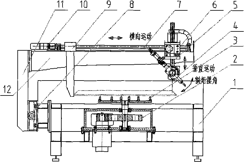
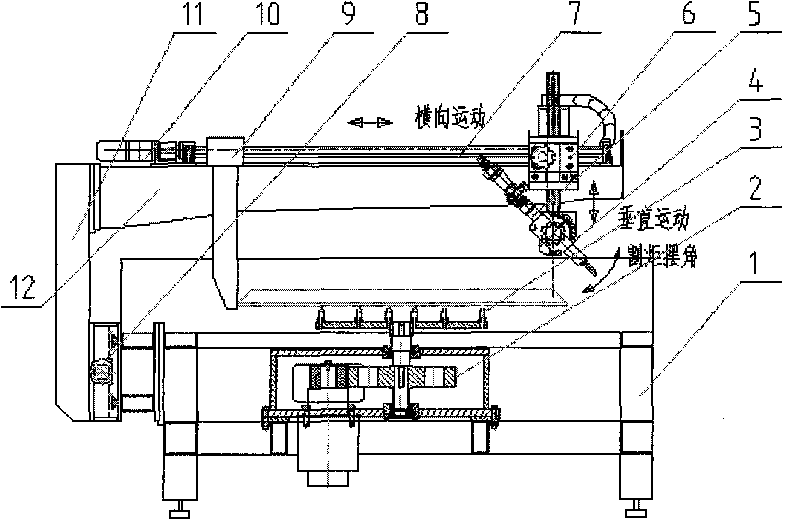
[0012] exist figure 1 and figure 2 In the embodiment of the method shown, the base (1) is the basis for the realization of the whole method, and the infinite rotary disk (3) of the workpiece and the power transmission (2) of the infinite rotary disk are installed in the middle. For the workpiece, a cutting torch longitudinal motion mechanism (8) is installed on the left side of the base (1) as shown in the figure. The longitudinal sliding plate (11) on the mechanism is driven by the cutting torch longitudinal driving device (15) to realize longitudinal movement, and the longitudinal sliding plate (11) ) is connected to the beam (12), on which a transverse linear motion mechanism (7) of the cutting torch is installed, and the transverse slide plate (14) on the mechanism is driven by the transverse driving device (10) of the cutting torch to realize transverse movement, A cutting torch lifting device (6) is installed on the transverse slide plate (14), a cutting torch swinging...


PUM


Abstract

The patent of the invention relates to an innovative numerical control cutting machining method aiming at (sheet metal) workpiece welding grooves, which is a cutting application method combining blaze, plasma and flying optics laser and belongs to the field of industrial welding and cutting technology. The invention adopts a machining mode that workpiece actively rotates, the workpiece can be freely clamped, the invention is suitable for numerical control cutting machining of the welding groove with any curved profiles, the cutting quality, the production efficiency and the material utilization are obviously enhanced, and the device cost is low. The invention adopts the mode that the workpiece revolves around tools (cutting torch) to rotate, thoroughly solves the technology bottlenecks of complex structure (winding and restrictions of connecting cables, gas pipelines, and the like of the cutting torch caused by the rotation of the workpiece) of traditional numerical control cutting method, and the like. The technical implementation scheme is that a workpiece active (unlimited) rotary disk arranged on a substrate loads the workpiece; each axis (A, X, Y, W and Z) of the numerical control procedure control system moves the edge of the workpiece groove to a cutting zone, and cutting torch (Z) axis automatically falls downwards to a working height and completes initial cutting gesture according to groove angle and thickness of the programming workpiece; and the workpiece (W) placed on the unlimited rotary disk is continuously matched with the cutting torch to swing (A) to do transverse (X) and longitudinal associated movement after a numerical control cutting processing program is operated, and the cutting torch is placed in a normal section of a cut workpiece all along and completes processing molding of the welding groove of the workpiece. The invention can be widely applied and popularized in industrial welding and cutting field.

Description

Technical field [0001] The patent of the present invention is an innovative numerical control cutting processing method for (metal plate) workpiece welding grooves, which can be combined with cutting applications of flame, plasma, and flying optical path lasers. It belongs to the technical field of industrial welding and cutting. Background technique [0002] At present, the traditional coordinate CNC cutting machine generally uses the cutting torch to cut perpendicular to the plate workpiece (commonly known as: blanking). For cutting torch processing, these traditional methods use the workpiece to be fixed, and the tool (cutting torch) moves around the workpiece, and there are many disadvantages as follows: [0003] ① When manual or semi-automatic trolleys are used to complete the straight line or curved welding groove processing on the edge of the workpiece contour, the motion track control is very complicated and the quality is difficult to guarantee; [0004] ② When us...

Claims


Application Information

Patent Timeline
IPC IPC(8): B23K37/00B23K37/047B23K37/02B23K37/04B23K7/00B23K7/10B23K10/00B23K26/38B23K26/42B23K26/02B23K26/08
Inventor 刘旭超陆元元孙义江尹权
Owner 北京林克曼数控技术股份有限公司
Why Eureka
Try Eureka