Contactless method of supplying power

Inactive Publication Date: 2013-10-31
DEPUY PROD INC +1
View PDF10 Cites 37 Cited by
  • Summary
  • Abstract
  • Description
  • Claims
  • Application Information

AI Technical Summary

Benefits of technology

[0011]The contactless method of supplying power described above has the characteristic that it can quickly, stably, and reliably detect foreign objects on the power supply stand with a simple circuit structure and low manufacturing cost. This is because the power supply stand adjusts its output while limiting output power to a power output threshold, and determines that a foreign object is on the power supply stand when increase-power-request signals are continuously detected for a preset time period. Here, increase-power-request signals and decrease-power-request signals are sent from the portable device to the power supply stand to adjust output power and the power supply stand adjusts output power below the power output threshold. In this contactless method of supplying power, if a (metal) foreign object is placed on the power supply stand, it will absorb power from the transmitting coil and transmission efficiency will drop. If transmission efficiency drops, portable device received power will decrease and become lower than the required power. In that situation, the portable device will output an increase-power-request signal. The power supply stand will detect the increase-power-request signal and increase its output, but it will limit its maximum output to the power output threshold value. In this case, even if power supply stand output is increased to the power output t

Problems solved by technology

If transmission efficiency drops, portable device received power will decrease and become lower than the required power.
In the contactless method of supplying power described above, foreign object presence is not determined by detecting f

Method used


Image

  • Contactless method of supplying power
  • Contactless method of supplying power
  • Contactless method of supplying power

Examples


Example

[0026]The following describes embodiments of the present invention based on the figures.

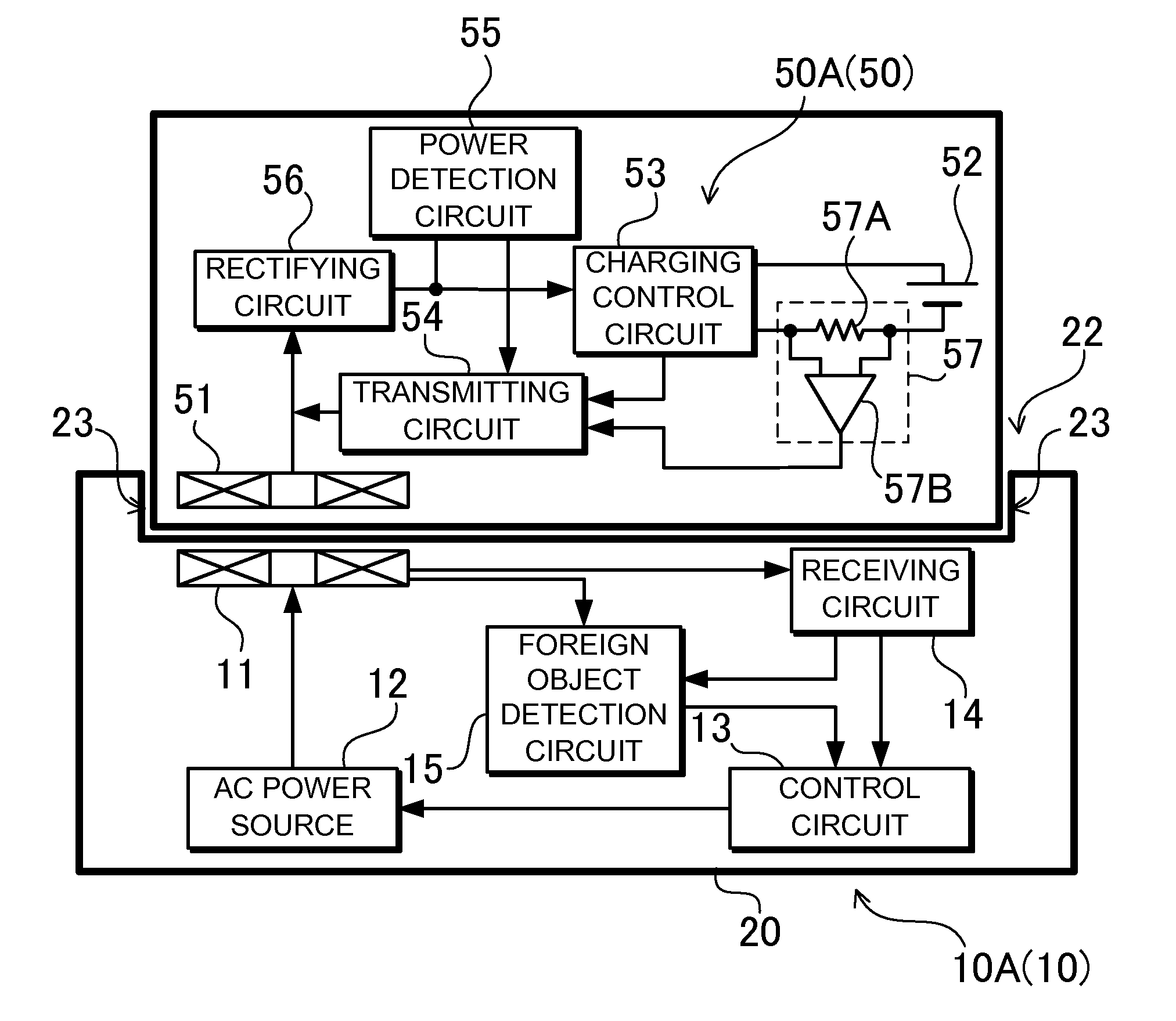
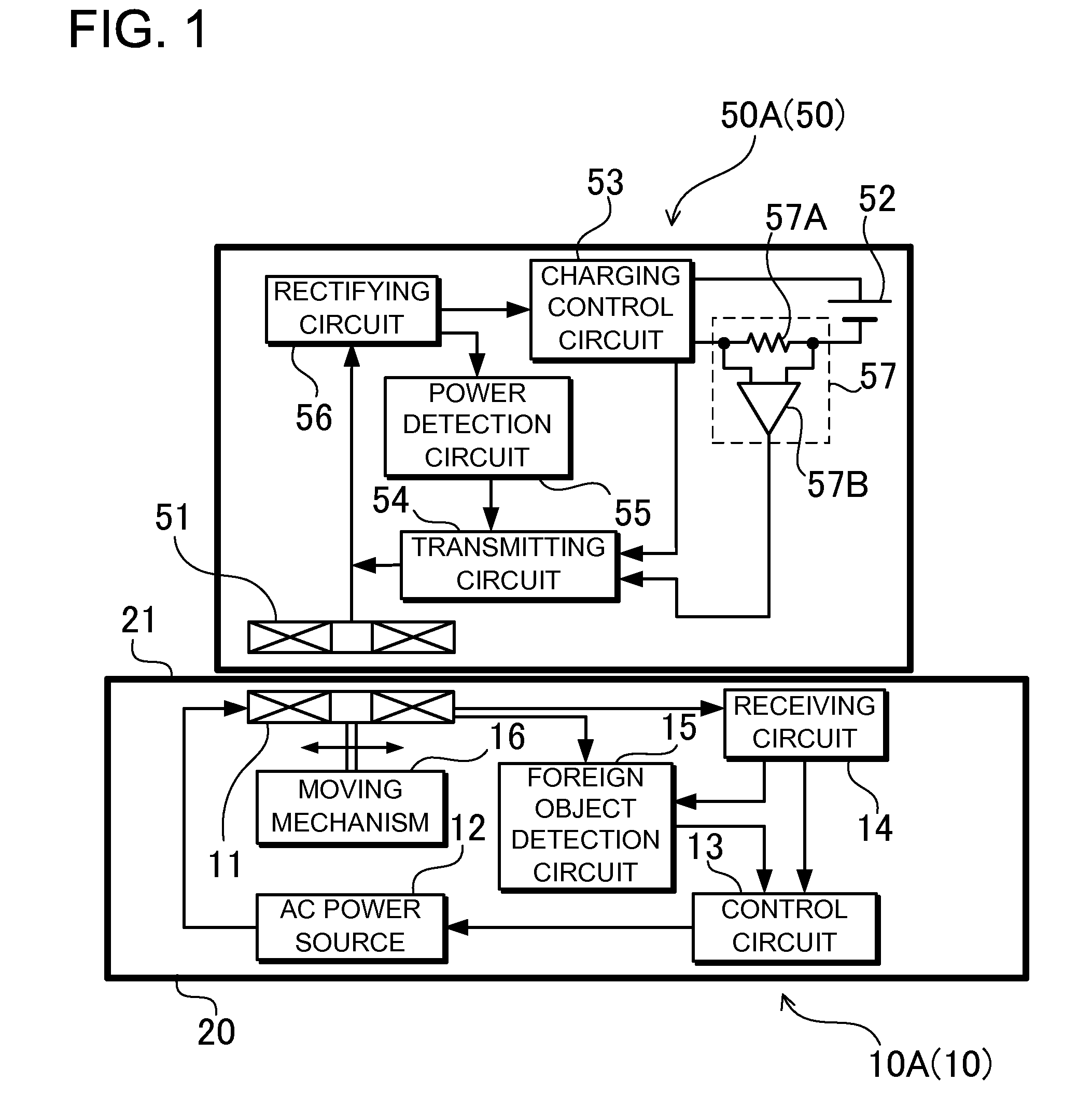
[0027]FIG. 1 is a block diagram showing a power supply stand that transmits power and portable device for the contactless method of supplying power of the present invention. This figure shows a portable device 50 placed on a power supply stand 10 to supply power from the power supply stand 10 to the portable device 50. In the embodiment described below, the power supply stand 10 is a charging pad 10A, the portable device 50 is a battery powered device 50A, and power is supplied from the charging pad 10A to the battery powered device 50A to charge a battery 52 housed in the battery powered device 50A.

[0028]However, the present invention does not limit the power supply stand to a charging pad and the portable device to a battery powered device. Power can also be supplied from the power supply stand to a portable device that is an illumination device or a charging adapter. A portable device that is ...


PUM


Abstract

Power supply stand output to the portable device is adjusted according to the power adjustment signals. Maximum power supply stand output is limited to a power output threshold value. The portable device compares the power received from the power supply stand to the required power. When the received power is lower than the required power, the portable device sends a power adjustment signal to the power supply stand, which is an increase-power-request signal. When the received power is greater than the required power, the portable device sends a decrease-power-request signal to the power supply stand. The power supply stand adjusts output and limits it to the power output threshold value. When continuous output of increase-power-request signals from the portable device is detected over a preset time period, a foreign object is determined to be on the power supply stand.

Description

BACKGROUND OF THE INVENTION[0001]1. Field of the Invention[0002]The present invention relates to a contactless (wireless) method of supplying power that disposes a transmitting coil and a receiving coil in close proximity to magnetically couple the coils to supply power from the transmitting coil to the receiving coil by magnetic induction, and in particular to a contactless method of supplying power that detects foreign objects on the power supply stand.[0003]2. Description of the Related Art[0004]A contactless method of supplying power that places a portable device housing a receiving coil on a power supply stand (pad, platform, stage, cradle) housing a transmitting coil and transmits power from the transmitting coil to the receiving coil has been developed. (Refer to Japanese Laid-Open Patent Publication 2008-17562.)[0005]In the contactless method of supplying power of the related disclosure, a charging pad serves as the power supply stand, a battery powered device serves as the ...

Claims


Application Information

Patent Timeline
IPC IPC(8): H02J17/00H02J7/02H02J7/00H04M1/02
CPCH02J17/00H02J7/025B60L53/124Y02T10/70Y02T10/7072Y02T90/14H02J50/60H02J50/10H02J50/90
Inventor IIJIMA, YASUHIROTOMIKI, MASAHIROARAI, YUJITANIDA, YOSUKE
Owner DEPUY PROD INC
Why Eureka
Try Eureka