Press section and permeable belt in a paper machine

a permeable belt and paper machine technology, applied in the field of paper machines, can solve the problems of limited open area, inefficient wet pressing methods, enp belts, etc., and achieve the effect of long dwell tim

Inactive Publication Date: 2010-07-08
VOITH PATENT GMBH
View PDF8 Cites 180 Cited by
  • Summary
  • Abstract
  • Description
  • Claims
  • Application Information

AI Technical Summary

Benefits of technology

[0017]An advantage of the present invention is that it allows substantial airflow therethrough to reach the fibrous web for the removal of water by way of a vacuum, particularly during a pressing operation.
[0018]Another advantage is that the permeable belt allows a significant tension to be applied thereto.
[0019]Yet another advantage is that the permeable belt has substantial open areas adjacent to contact areas along one side of the belt.
[0020]Still yet another advantage of the present invention is that the permeable belt is capable of applying a line force over an extremely long nip, thereby ensuring a long dwell time in which pressure is applied against the web as compared to a standard shoe press.
[0021]The invention also provides for a belt press for a paper machine, wherein the belt press comprises a roll comprising an exterior surface. A permeable belt comprises a first side and is guided over a portion of the exterior surface of the roll. The permeable belt has a tension of at least approximately 30 KN / m. The first side has an open area of at least approximately 25% a contact area of at least approximately 10%, preferably a contact area of at least 25%.
[0022]The first side may face the exterior surface and the permeable belt may exert a pressing force on the roll. The permeable belt may have through openings. The permeable belt may have through openings arranged in a generally regular symmetrical pattern. The permeable belt may include generally parallel rows of through openings, whereby the rows are oriented along a machine direction. The permeable belt may exert a pressing force on the roll in the range of between approximately 30 KPa and approximately 300 KPa (approximately 0.3 bar to approximately 1.5 bar and preferably approximately 0.07 to approximately 1 bar). The permeable belt may have through openings and a plurality of grooves, each groove intersecting a different set of through openings. The first side may face the exterior surface and the permeable belt may exert a pressing force on the roll. The plurality of grooves may be arranged on the first side. Each of the plurality of grooves may comprise a width, and each of the through openings may comprise a diameter, and wherein the diameter is greater than the width.

Problems solved by technology

It has been recognized that conventional wet pressing methods are inefficient in that only a small portion of a roll's circumference is used to process the paper web.
A problem with such an approach is that the impermeable belt prevents the flow of a drying fluid, such as air through the paper web.
However, such a system with the ENP belt has disadvantages, such as a limited open area.
Huge TAD-cylinders are necessary, however, and as well as a complex air supply and heating system.
This system also requires a high operating expense to reach the necessary dryness of the web before it is transferred to a Yankee Cylinder, which drying cylinder dries the web to its end dryness of approximately 97%.
The machinery of the TAD system is very expensive and costs roughly double that of a conventional tissue machine.
Also, the operational costs are high, because with the TAD process it is necessary to dry the web to a higher dryness level than it would be appropriate with the through air system in respect of the drying efficiency.
The reason is the poor CD moisture profile produced by the TAD system at low dryness level.

Method used


Image

  • Press section and permeable belt in a paper machine
  • Press section and permeable belt in a paper machine
  • Press section and permeable belt in a paper machine

Examples


Embodiment Construction

[0087]The particulars shown herein are by way of example and for purposes of illustrative discussion of the embodiments of the present invention only and are presented in the cause of providing what is believed to be the most useful and readily understood description of the principles and conceptual aspects of the present invention. In this regard, no attempt is made to show structural details of the present invention in more detail than is necessary for the fundamental understanding of the present invention, the description is taken with the drawings making apparent to those skilled in the art how the forms of the present invention may be embodied in practice.

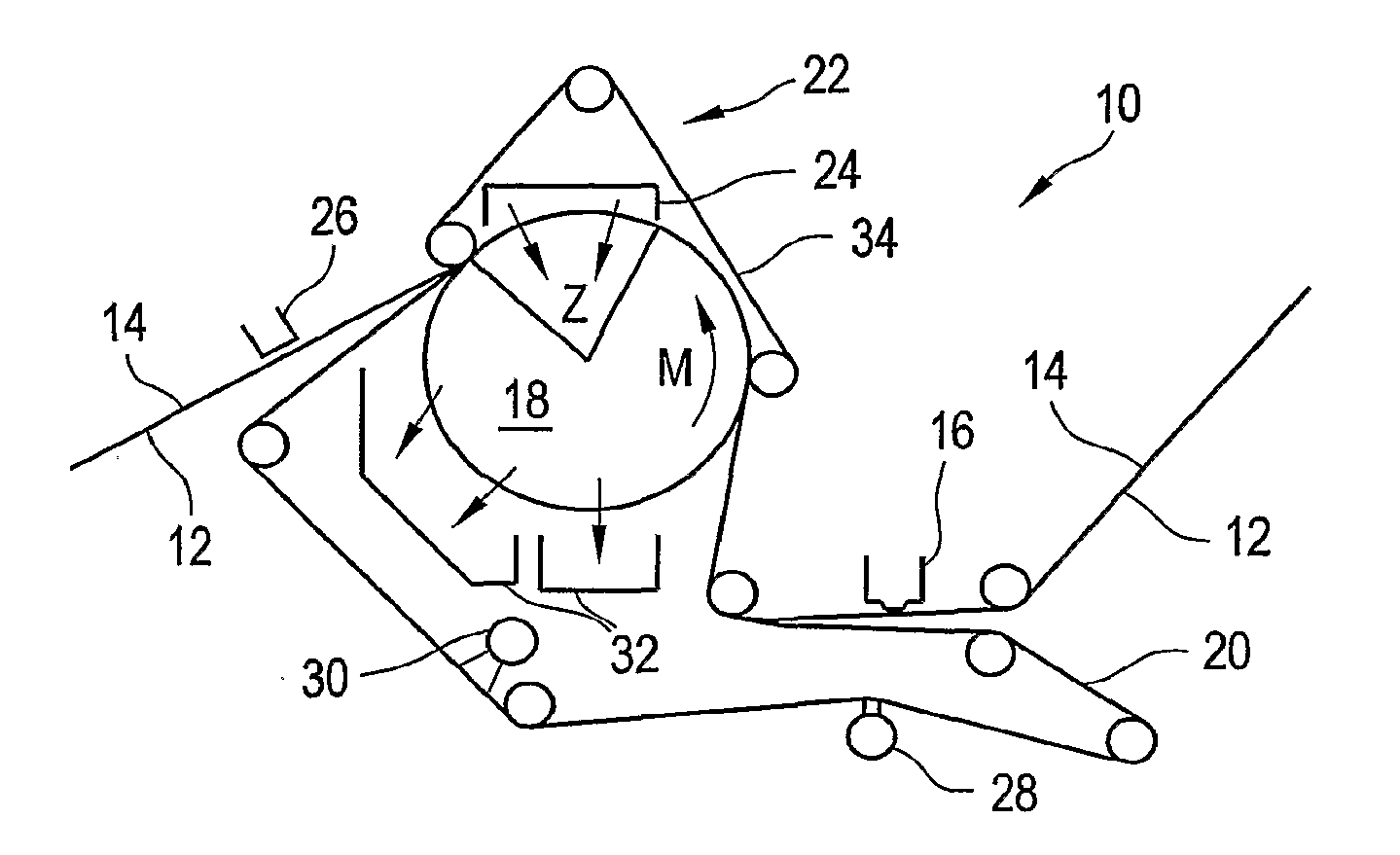
[0088]Referring now to the drawings, and more particularly to FIG. 1, there is shown an advanced dewatering system 10 for processing a fibrous web 12. System 10 includes a fabric 14, a suction box 16, a vacuum roll 18, a dewatering fabric 20, a belt press assembly 22, a hood 24 (which may be a hot air hood), a pick up suction ...


PUM


Abstract

A pressing arrangement including at least one first fabric and second fabric both being permeable. A paper web is disposed between the first fabric and the second fabric. A pressure producing element is in contact with the first fabric. A support surface of a supporting structure is in contact with the second fabric. A differential pressure is provided between the first fabric and the support surface that acts on the first fabric, the paper web, and the second fabric, whereby the paper web is subjected to mechanical pressure and experiences a predetermined hydraulic pressure so as to cause water to be drained from the paper web. The pressing arrangement is structured and arranged to allow air to flow in a direction from the first fabric through the paper web and through the second fabric.

Description

CROSS REFERENCE TO RELATED APPLICATIONS[0001]This is a division of U.S. patent application Ser. No. 10 / 587,627, entitled “PRESS SECTION AND PERMEABLE BELT IN A PAPER MACHINE”, filed Jul. 28, 2006, which is incorporated herein by reference.BACKGROUND OF THE INVENTION[0002]1. Field of the Invention[0003]The present invention relates to a paper machine, and, more particularly, to a permeable belt used in a belt press in a paper machine.[0004]2. Description of the Related Art[0005]In a wet pressing operation, a fibrous web sheet is compressed at a press nip to the point where hydraulic pressure drives water out of the fibrous web. It has been recognized that conventional wet pressing methods are inefficient in that only a small portion of a roll's circumference is used to process the paper web. To overcome this limitation, some attempts have been made to adapt a solid impermeable belt to an extended nip for pressing the paper web and dewater the paper web. A problem with such an approac...

Claims


Application Information

Patent Timeline
Patent Type & Authority Applications(United States)
IPC IPC(8): D21F11/00D21F3/08
CPCD21F3/045D21F11/006D21F11/14D21F11/145
Inventor SCHERB, THOMAS THOROEWALKENHAUS, HUBERTHERMAN, JEFFREYSILVA, LUIZ CARLOS
Owner VOITH PATENT GMBH
Why Eureka
Try Eureka