Eureka AIR delivers breakthrough ideas for toughest innovation challenges, trusted by R&D personnel around the world.

Belt unit and image forming apparatus

a technology of belt unit and belt roller, which is applied in the direction of electrographic process, instruments, transportation and packaging, etc., can solve the problems of enlarge the load on the shift prevention portion of the belt which restrains the shift of the belt, and the tension difference directly becomes a burden on the belt and the roller

Active Publication Date: 2006-07-13
BROTHER KOGYO KK
View PDF6 Cites 15 Cited by
  • Summary
  • Abstract
  • Description
  • Claims
  • Application Information

AI Technical Summary

Benefits of technology

[0013] In the technique mentioned above, the outer diameter of the roller on one end side is made larger than on the other end side (JP-A-08-190319), or the two rollers are held in a positional relationship having an angle therebetween (JP-A-2002-268455), whereby the peripheral length of the belt on one end side of this belt in the widthwise direction thereof is made greater so as to make the tension of this part larger.
[0015] The present invention has been made in view of the above circumstances and provides a technique for making a load on the unit smaller than in the related art, in preventing the shift of the belt toward the end side of the roller.

Problems solved by technology

Therefore, such a tensional difference directly becomes burdens to the belt and the rollers.
Besides, since the force of shifting the belt increases due to such a tensional difference, also a load on the shift prevention portion which restrains the shift of the belt enlarges.

Method used


Image

  • Belt unit and image forming apparatus
  • Belt unit and image forming apparatus
  • Belt unit and image forming apparatus

Examples


Embodiment Construction

[0021] Now, embodiments will be described with reference to the drawings.

[0022] 1. General Configuration

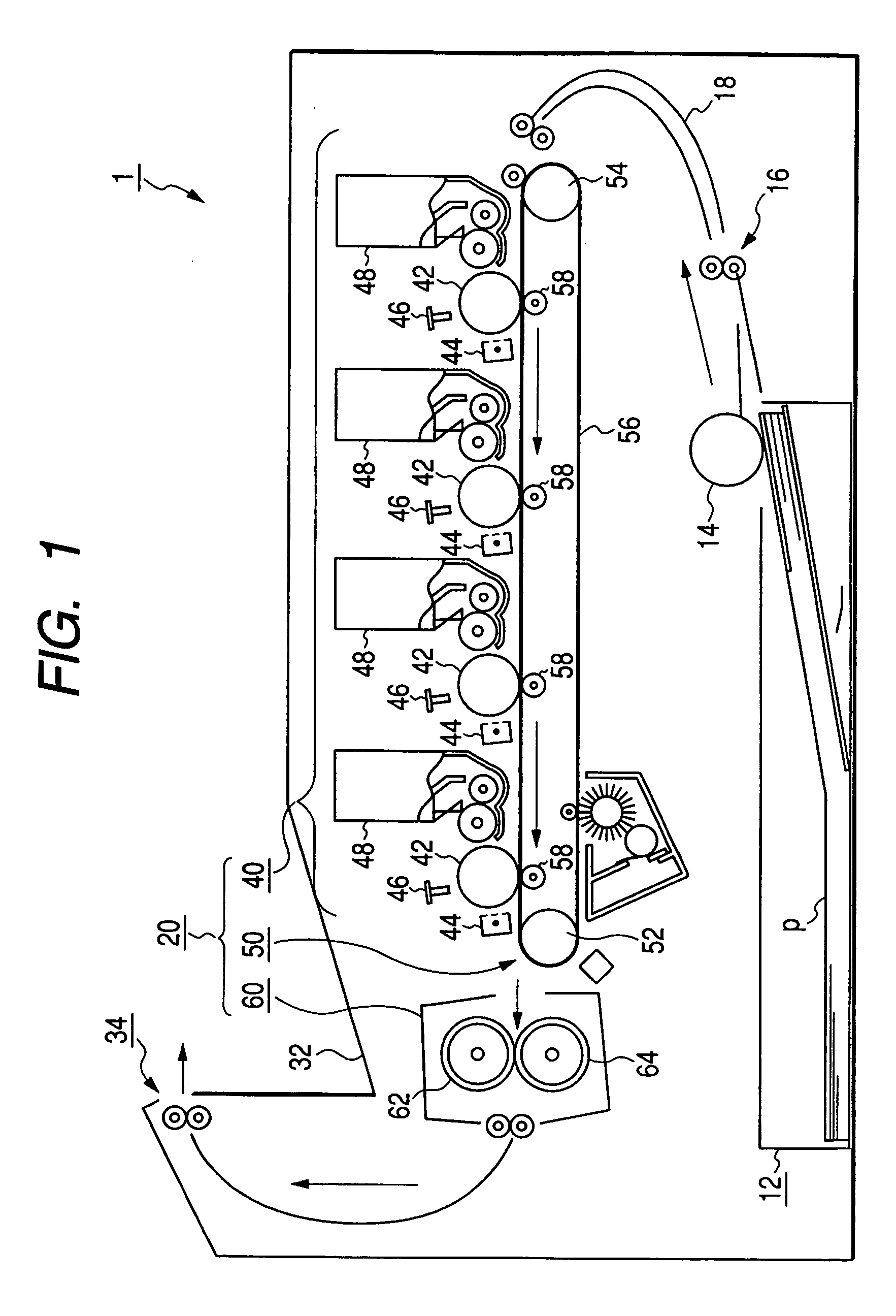
[0023] As shown in FIG. 1, a color laser printer (hereinafter, simply termed “printer”) 1 is an image forming apparatus in which a housing accommodates therein a sheet-of-paper tray 12 that is attachable and detachable in a state where record sheets of paper p are set, a paper feed roller 14 that extracts the record sheets of paper p set in the sheet-of-paper tray 12, one by one, a pair of conveyance rollers 16 that convey the record sheet of paper p extracted by the paper feed roller 14, a guide path 18 that guides the record sheet of paper p conveyed by the conveyance rollers 16, an image formation section 20 that forms images on the record sheet of paper p conveyed in through the guide path 18, a pair of paper ejection rollers 34 that eject the record sheet of paper p formed with the images by the image formation section 20, into an ejection tray 32, and so forth.

[0024] The ...


PUM


Abstract

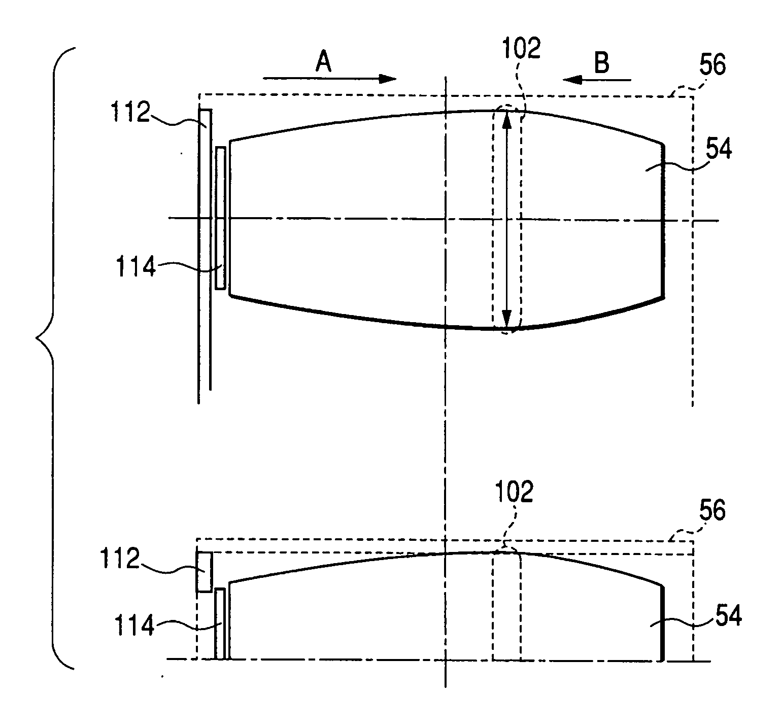
A belt unit includes a plurality of rollers including a driving roller and a driven roller; a belt being supported by the plurality of rollers; a specified roller; and a shift restraint member restraining the belt from shifting toward one end side of the specified roller. The specified roller is at least one roller of the plurality of rollers. The specified roller has such a shape that an outer diameter thereof on each of both end sides thereof is continuously enlarged toward a central part thereof in an axial direction thereof, and has such a shape that a region where the outer diameter thereof is the largest is shifted onto one end side thereof with respect to the central part thereof in the axial direction thereof within a belt suspension range.

Description

CROSS-REFERENCE TO RELATED APPLICATIONS [0001] This application is based on and claims the benefit of priority from the prior Japanese Patent Application No. 2004-381913, filed on Dec. 28, 2004; the entire contents of which are incorporated herein by reference. BACKGROUND OF THE INVENTION [0002] 1. Field of the Invention [0003] The present invention relates to a belt unit in which a belt is supported by a plurality of rollers including a driving roller and a driven roller, a roller which can configure the belt unit, and an image forming apparatus which forms an image on a record medium while conveying the record medium by the belt unit. [0004] 2. Description of the Related Art [0005] Heretofore, in a belt unit in which a belt is extended between a driving roller and a driven roller, various configurations have been proposed as measures for preventing a situation where the belt shifts in the widthwise direction thereof, that is, where the position of the belt shifts toward either end...

Claims


Application Information

Patent Timeline
IPC IPC(8): B65H5/02
CPCB41J11/007G03G15/1625G03G2215/00143
Inventor MORI, HIROTAKA
Owner BROTHER KOGYO KK
Why Eureka
Eureka Blog
Learn More