Electromagnetic relay

a technology of electromagnetic relays and relays, applied in electromagnetic relay details, high-tension/heavy-dress switches, air-break switches, etc., can solve the problems of contact wear, contact melting, cost rise, etc., and achieve the effect of preventing arc cooling plate damag

Active Publication Date: 2014-06-05
FUJITSU COMPONENENT LTD
View PDF8 Cites 42 Cited by
  • Summary
  • Abstract
  • Description
  • Claims
  • Application Information

AI Technical Summary

Benefits of technology

[0016]In the electromagnetic relay according to the present invention, between pole faces an arc which is pulled into a space between pole faces contacts the first surface of at least one of the arc cooling plates. For this reason, arcs which are generated by fixed contacts and moving contacts are cooled and extinguished by contact with the arc cooling plates. Further, high temperature arcs are extinguished by contact with arc cooling plates in the stretched state, so the loads on the arc cooling plates become smaller and it is possible to prevent damage to the arc cooling plates by the arcs.

Problems solved by technology

Further, even if the circuit is broken, the arc sometimes causes wear of contacts or melting of the contacts or other problems.
Therefore, the cost rises.

Method used


Image

  • Electromagnetic relay
  • Electromagnetic relay
  • Electromagnetic relay

Examples


Embodiment Construction

[0022]Below, the attached figures will be referred to so as to explain the embodiments of the present invention. In the following embodiments, the same or similar members are shown assigned common reference signs. Further, it should be noted that the technical scope of the present invention is not limited to these embodiments and extends to the inventions which are described in the claims and their equivalents.

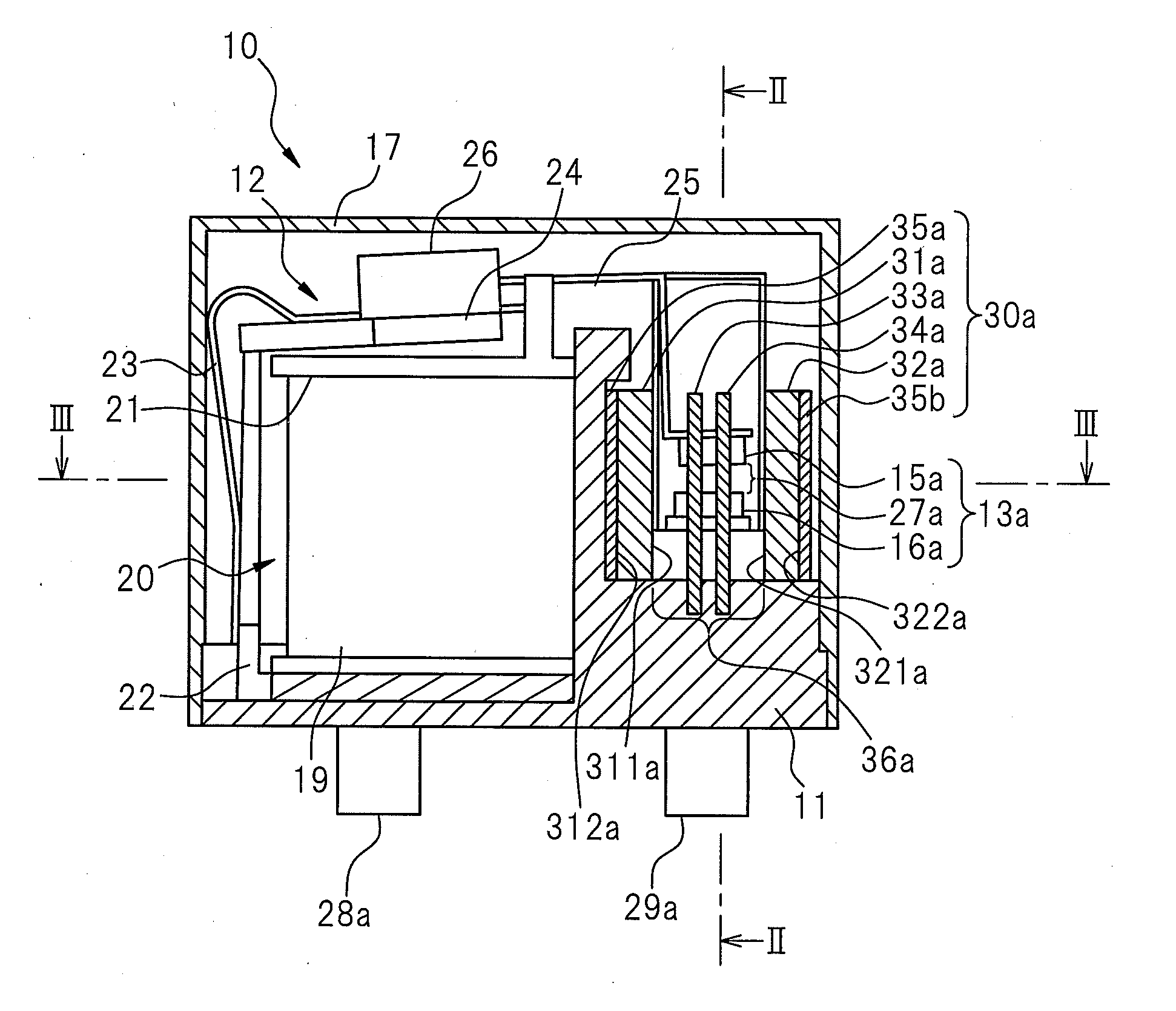
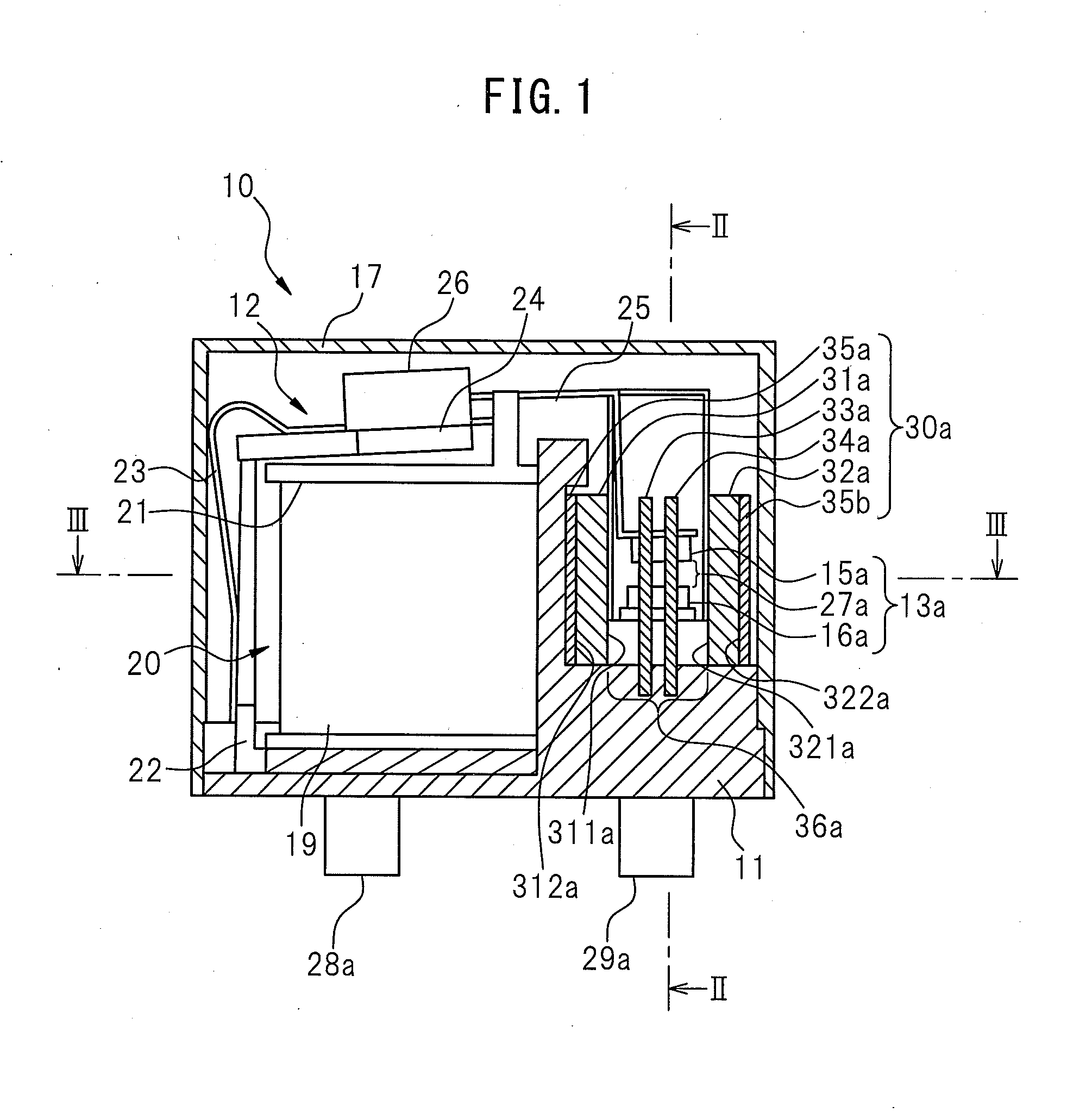
[0023]FIG. 1 is a cross-sectional view which shows the configuration of an electromagnetic relay 10 according to an embodiment of the present invention, FIG.

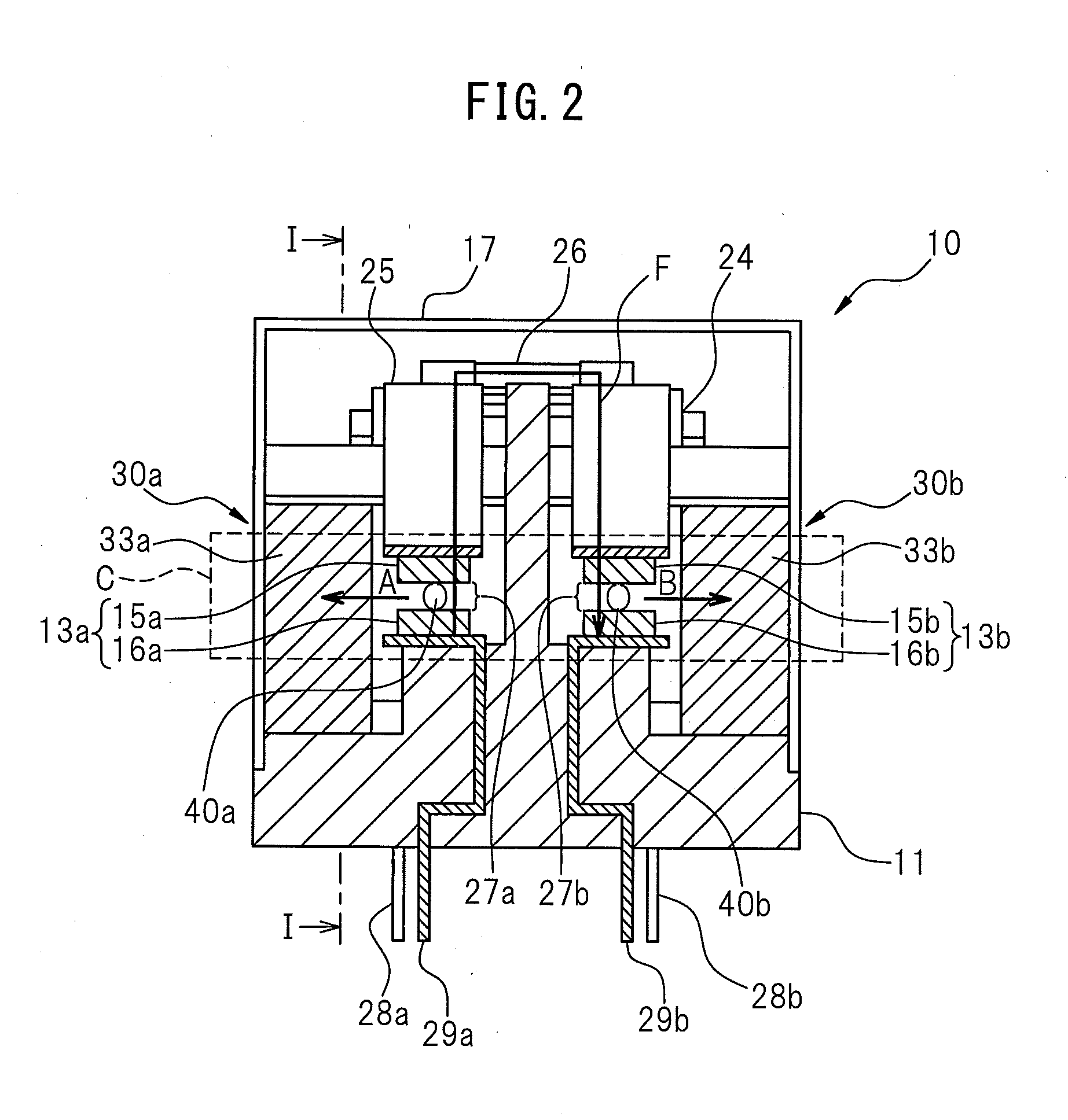
[0024]2 is a cross-sectional view along the line II-II of FIG. 1, and FIG. 3 is a cross-sectional view along the line III-III of FIG. 1. The electromagnetic relay 10 of the present embodiment comprises a base 11, an electromagnet block 12, contacts 13a, 13b (hereinafter sometimes collectively referred to as “contacts 13”) which include two fixed contacts 16a, 16b (hereinafter sometimes together referred to as “fixed contac...


PUM


Abstract

An electromagnetic relay which is improved in arc blocking performance without being increased in size is desired. An electromagnetic relay according to the present invention is provided with a fixed contact, a moving contact which is movable respect to the fixed contact, a pair of magnets which is arranged at the side of the fixed contact and the moving contact so that pole faces with mutually reversed polarity are separated from and face each other and a pair of arc cooling plates which is arranged in a spaces between the magnets and which has first surfaces which face each other across a gap and second surfaces which face a pole face of either of the magnets, respectively.

Description

TECHNICAL FIELD[0001]The present invention relates to an electromagnetic relay.BACKGROUND ART[0002]In an electromagnetic relay which is used inside a circuit of a high voltage battery of an electric vehicle or large-sized direct current device etc., sometimes the arc discharge which occurs at the time the contacts are opened (hereinafter simply referred to as an “arc”) causes the conduction state to be maintained and prevents the circuit from being broken. Further, even if the circuit is broken, the arc sometimes causes wear of contacts or melting of the contacts or other problems. Therefore, to secure the performance which is demanded from an electromagnetic relay which is used for a direct current high voltage circuit, it is essential to improve the arc extinguishing performance. Patent documents 1 to 4 disclose electromagnetic relays which are provided with devices for extinguishing the arcs which are generated at the time the contacts open or methods of extinguishing the arcs.[0...

Claims


Application Information

Patent Timeline
Patent Type & Authority Applications(United States)
IPC IPC(8): H01H33/18
CPCH01H33/182H01H9/36H01H9/443H01H50/546
Inventor HIRAIWA, NOBUYOSHISAITO, YASUSHINAGAMINE, KAZUTAKAKAKOIYAMA, YUKIWU, YANFENG
Owner FUJITSU COMPONENENT LTD
Why Eureka
Try Eureka