Measuring transducer of vibration-type

a technology of measuring transducers and vibration types, applied in the direction of mass flow measurement devices, measurement devices, instruments, etc., can solve the problems of only being able to compensate transverse forces of the same frequency in a very limited extent, only with a very high technical effort, and practically the same disadvantage, so as to improve the ability of the measuring transducer to withstand near- and long-term operating conditions, and reduce the effect of mechanical loading

Active Publication Date: 2008-10-16
ENDRESS HAUSER FLOWTEC AG
View PDF23 Cites 43 Cited by
  • Summary
  • Abstract
  • Description
  • Claims
  • Application Information

AI Technical Summary

Benefits of technology

[0049]An advantage of the invention is that, by the positioning of the tie-down points of the respective connection lines on laterally comparatively little-moved sections of the inner part, due to the comparatively small mechanical loading of the same, it is possible to obtain not only a significant stabilizing of the zero point, but also improvement of the ability of the measuring transducer to withstand near- and long-term operating conditions.
is that, by the positioning of the tie-down points of the respective connection lines on laterally comparatively little-moved sections of the inner part, due to the comparatively small mechanical loading of the same, it is possible to obtain not only a significant stabilizing of the zero point, but also improvement of the ability of the measuring transducer to withstand near- and long-term operating conditions.

Problems solved by technology

On the other hand, a significant problem of the above-described measuring transducers lies in the fact that, because of the alternating lateral deflections of the vibrating, single measuring tube, oscillating transverse forces of the same frequency can be caused to act on the pipeline.
To this point in time, these transverse forces have only been able to be compensated to a very limited extent and only with a very high technical effort.
In contrast, those measuring transducers, especially those disclosed in U.S. Pat. No. 5,531,126 or U.S. Pat. No. 5,969,265, in the case of applications with media having densities fluctuating over wide ranges, especially in the case of different media following one after the other, and even when to only a slight degree, exhibit practically the same disadvantage as measuring transducers without counteroscillators, since the above-mentioned net resultant forces are also dependent on the density of the medium and consequently can be different from zero to a considerable degree.
A great disadvantage of such a measuring transducer is, among other things, however, that the counteroscillator mass required for achieving a sufficiently robust damping increases more than proportionately with the nominal diameter of the measuring tube.
Investigations on measuring transducers of the described kind have, however, shown, that, despite the inner part, as discussed above, being almost perfectly mechanically balanceable, even in the case of fluctuating density, still considerable disturbances can arise in the oscillation measurement signals.
Especially, it has been found, firstly, that these disturbances are not only of equal frequency to the oscillations of the measuring tube, but also that these disturbances unfortunately also present themselves directly in the phase difference essential for the mass flow measurement and, consequently, can lead to a not inconsiderable corruption of the measurement result.
Additionally, these disturbances can arise in rather non-reproducible, and, as a result, without extra effort, unpredictable, manner.
Accompanying this, a subsequent, for example even algorithmic, compensation of these disturbances of the measurement signals is practically impossible.
Further, it has been found, that, especially in the sections of the connection lines, which extend practically freely suspended between the inner part and the transducer housing, interference voltages, or currents, can be induced directly in the connection lines, when the inner part is oscillating.
These interference voltages, or currents, are induced due to movements of the individual connection lines relative to one another, leading to changes with time of the capacitive and inductive line- and / or stray-impedances.
Making the situation even more difficult, these zero-point displacements caused by the connection lines depend in quite significant measure on the operating-temperature and / or -duration of the measuring transducer.
By the relative movement of the two tie-down points in each case intercepting the freely suspended line sections, the thereby necessarily deformed and / or moved line sections bring about their damping action, in such case, unfortunately in a manner such that the phase difference between the two sensor signals is changed.
However, it was, unfortunately, also determined, that the aforementioned zero-point error again is of considerable degree at just a very small departure from the perfectly central position, for instance even at the order of magnitude of manufacturing and / or mounting tolerances, and, associated therewith, at only a small eccentricity of the effective damping force or also a small asymmetry of a damping force burden relative to the mentioned oscillation node; this is true even more so in the case of a counteroscillator oscillating with considerable amplitude.
Accordingly, the connection lines can, both for electrical reasons and for reasons of mechanical strength, not be kept arbitrarily thin, and, along therewith, cannot be made mechanically insignificant as regards the zero-point error.

Method used


Image

  • Measuring transducer of vibration-type
  • Measuring transducer of vibration-type
  • Measuring transducer of vibration-type

Examples


Embodiment Construction

[0060]While the invention is susceptible to various modifications and alternative forms, exemplary embodiments thereof have been shown by way of example in the drawings and will herein be described in detail. It should be understood, however, that there is no intent to limit the invention to the particular forms disclosed, but on the contrary, the intention is to cover all modifications, equivalents, and alternatives falling within the spirit and scope of the invention as defined by the intended claims.

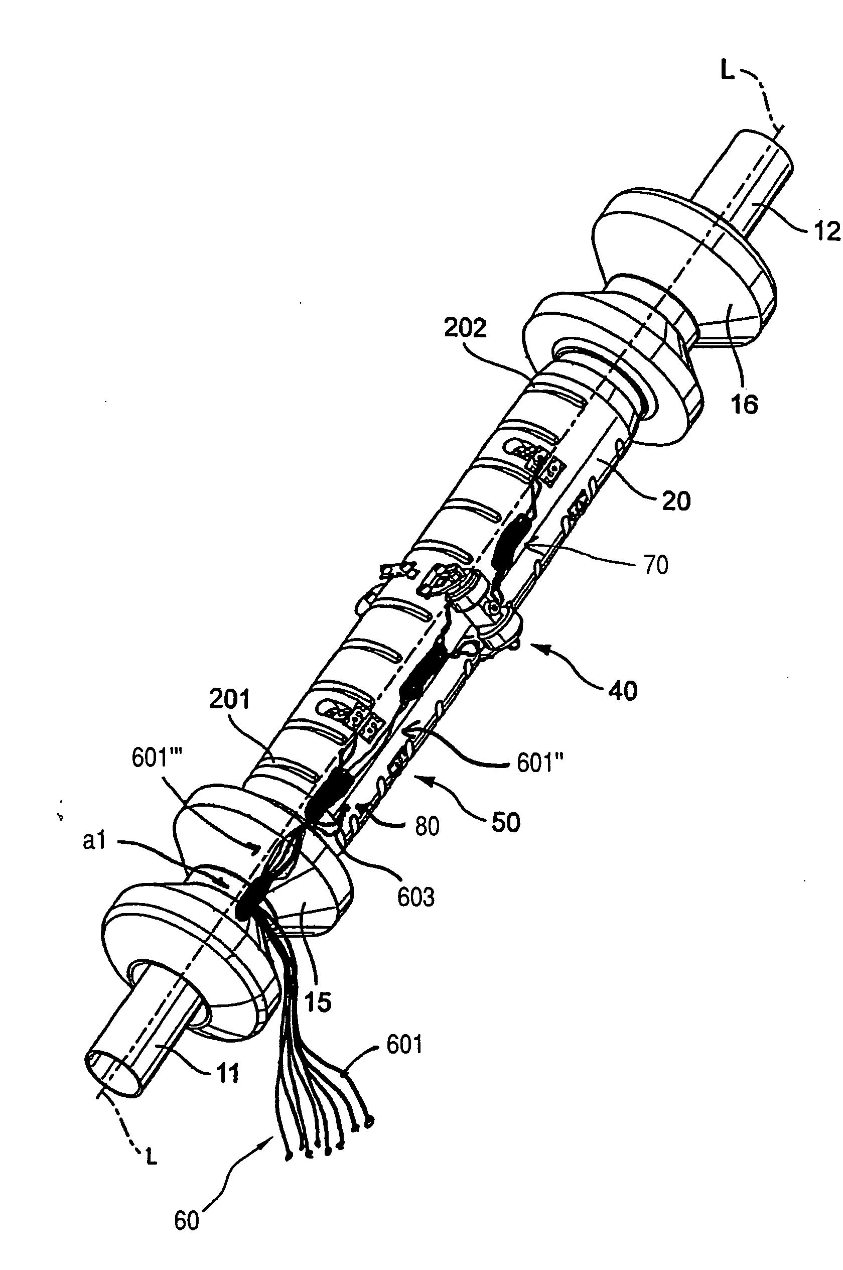
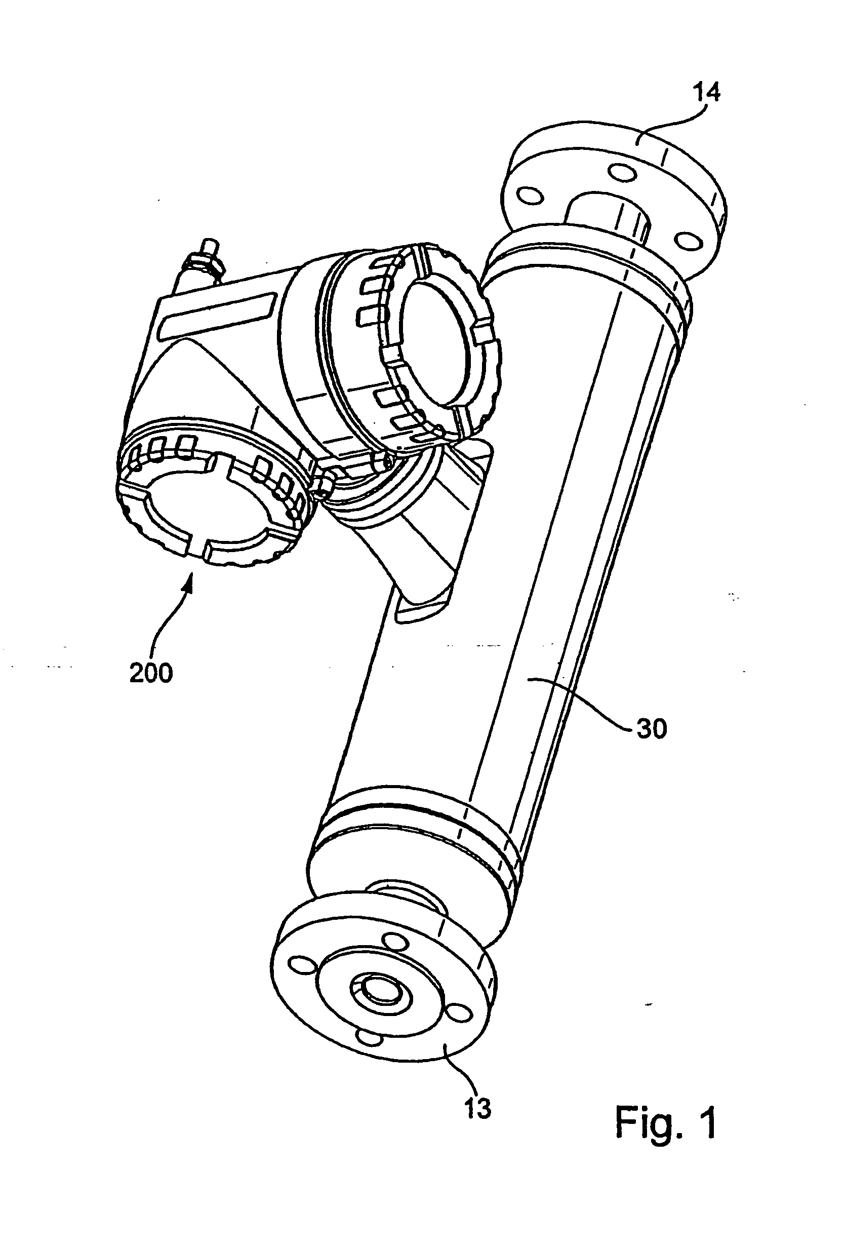
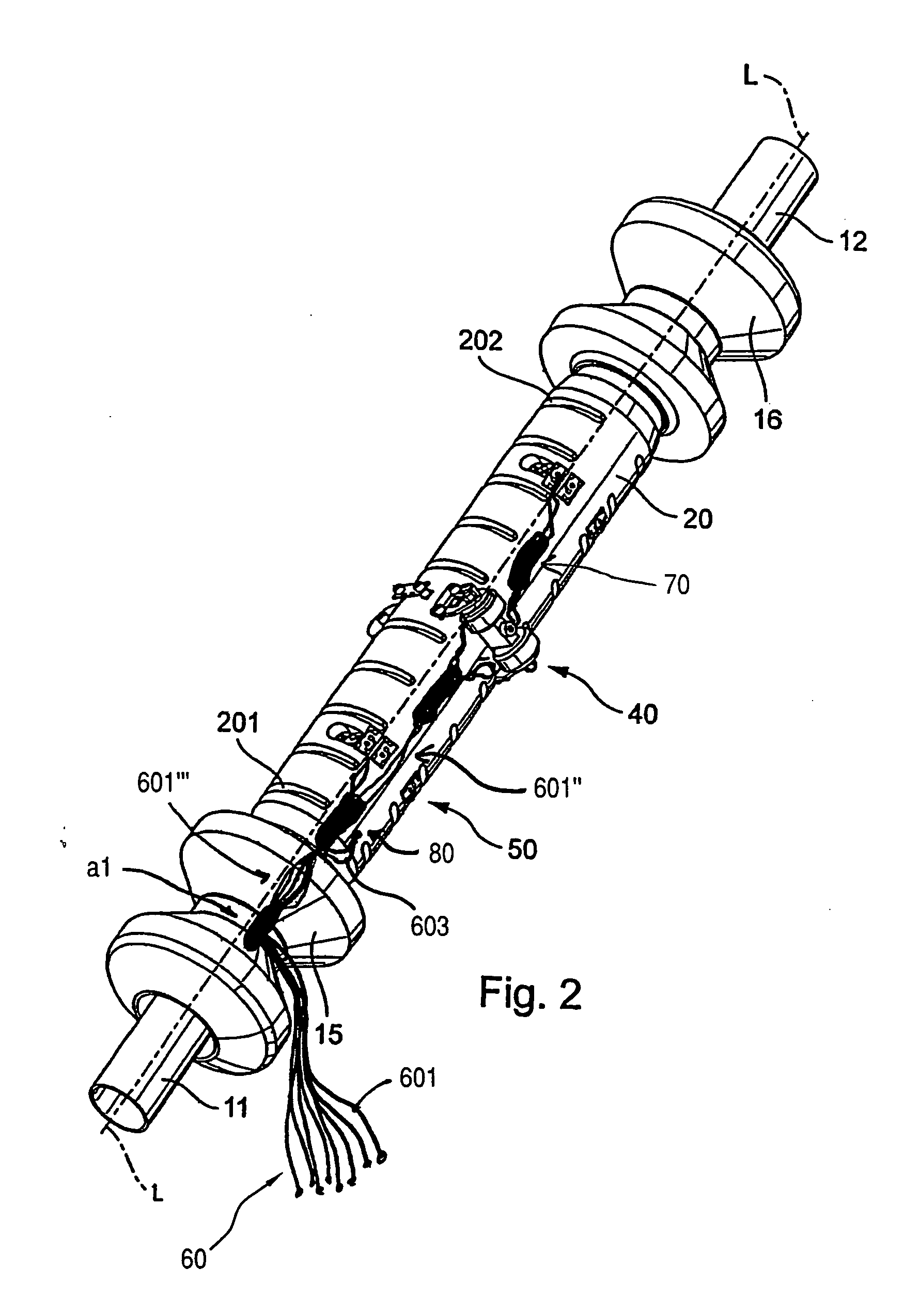
[0061]Shown in FIG. 1 is an inline measuring device insertable into a pipeline (not shown), for example, as a Coriolis mass flow measuring device, a density measuring device, a viscosity measuring device, or the like, which serves for measuring and / or monitoring at least one parameter, for example, a mass flow rate, a density, a viscosity, etc., of a medium flowing in the pipeline. The inline measuring device includes for such purpose a measuring transducer of vibration-type, through ...


PUM


Abstract

A measuring transducer includes: A measuring tube vibrating, at least at times, during operation and serving for conveying a medium, wherein the measuring tube communicates with a pipeline via an inlet tube piece at an inlet end and an outlet tube piece at an outlet end; a counteroscillator, which is affixed to the measuring tube on the inlet end to form a first coupling zone and affixed to the measuring tube on the outlet end to form a second coupling zone; and a transducer housing affixed to the inlet tube piece and the outlet tube piece. An exciter mechanism, for driving at least the measuring tube, and a sensor arrangement, for registering oscillations at least of the measuring tube, are, in each case, secured, at least in part, to the counteroscillator. Additionally, on the inlet side, an cantilever is so coupled in the region of the coupling zone with the inlet tube piece and the measuring tube, that the center of mass of the cantilever lies in the region of the inlet tube piece, and, on the outlet side, an cantilever is so coupled in the region of the coupling zone with the outlet tube piece and the measuring tube, that the center of mass of the cantilever lies in the region of the outlet tube piece. Furthermore, the measuring transducer includes connection lines, especially connection lines for the exciter mechanism and / or for the sensor arrangement, with at least one of the connection lines being secured to at least one of the two cantilevers.

Description

CROSS-REFERENCES[0001]This application is a nonprovisional application of U.S. Provisional Applications 60 / 877,130 filed on Dec. 27, 2006, 60 / 877,131 filed on Dec. 27, 2006, and 60 / 877,132 filed on Dec. 27, 2006 and claims the benefit of German applications 102006062185.9 filed on Dec. 22, 2006, 102006062219.7 filed on Dec. 22, 2006, and 102006062220.0 filed on Dec. 22, 2006.FIELD OF THE INVENTION[0002]The invention relates to a measuring transducer of vibration-type, especially one suited for use in a Coriolis mass-flow meter.BACKGROUND OF THE INVENTION[0003]For determining parameters, for example a mass flow (e.g. mass flow rate), a density, a viscosity, etc., of media, for example liquids and / or gases, flowing in a pipeline, often inline measuring devices are used, especially inline measuring devices embodied as Coriolis mass flow meters, which by means of a measuring transducer of vibration-type and a control and evaluation electronics connected thereto, induce forces, for examp...

Claims


Application Information

Patent Timeline
Patent Type & Authority Applications(United States)
IPC IPC(8): G01F1/84
CPCG01F1/8409G01F1/8413G01F1/8418G01F1/8422G01F1/8427G01F1/849G01F15/024
Inventor RIEDER, ALFREDFUCHS, MICHAELPROBST, LEONHARDWIESMANN, MICHAEL
Owner ENDRESS HAUSER FLOWTEC AG
Why Eureka
Try Eureka