Backpack frame and bag system

a frame and bag technology, applied in the field of backpack frame and bag system, can solve the problems of affecting the balance and stability of users, the need to carry heavy, oversized or awkwardly shaped objects, and the load is not well balanced and carried, so as to reduce or eliminate inadvertent sliding or shifting, and maintain the general shap

Active Publication Date: 2010-07-15
MYSTERY RANCH
View PDF20 Cites 18 Cited by
  • Summary
  • Abstract
  • Description
  • Claims
  • Application Information

AI Technical Summary

Benefits of technology

[0006]Portions of the frame and pack bag may be comprised of or include patches of a material designed to reduce or eliminate inadvertent sliding or shifting any cargo carried between the frame and pack bag. The pack bag, in order to maintain its general shape when not directly mounted to the frame, can include stiffening members. In one embodiment, the pack bag has stiffening members located about its front panel. In one configuration, the pack bag is attached directly to and relatively snugly against the frame and may include a collar for hanging the pack bag on a top portion of the frame.

Problems solved by technology

Often, backpack users have the need to carry heavy, oversized or awkwardly shaped objects.
When these oversized objects are attached to the outside of the pack bag, the result is a load that is not well balanced and does not carry well.
For instance, if a heavy object is attached to the back side of the pack bag, it will adversely affect the user's balance and stability, as the load is usually placed relatively far away from the user's back and center of gravity.
Furthermore, when long objects, such as mortar tubes and firearms, are strapped to the bag, they often sway thereby further hindering the user's balance.
Additionally, long objects, especially when positioned horizontally across the user's back or when allowed to sway, increase the user's overall width, which can have adverse impacts in crowded environments and tight surroundings.
Furthermore, in addition to carrying oversized objects, users often desire to also carry a pack bag for transporting smaller contents.

Method used


Image

  • Backpack frame and bag system
  • Backpack frame and bag system
  • Backpack frame and bag system

Examples


Embodiment Construction

[0017]The invention will now be described with reference to the drawing figures, in which like reference numerals refer to like parts throughout. For purposes of clarity in illustrating the characteristics of the present invention, proportional relationships of the elements have not necessarily been maintained in the drawing figures. The description of the invention will use terms such as vertical, horizontal, top and bottom. These terms are used to describe the components of the backpack system 10 when it is in its normal upright orientation.

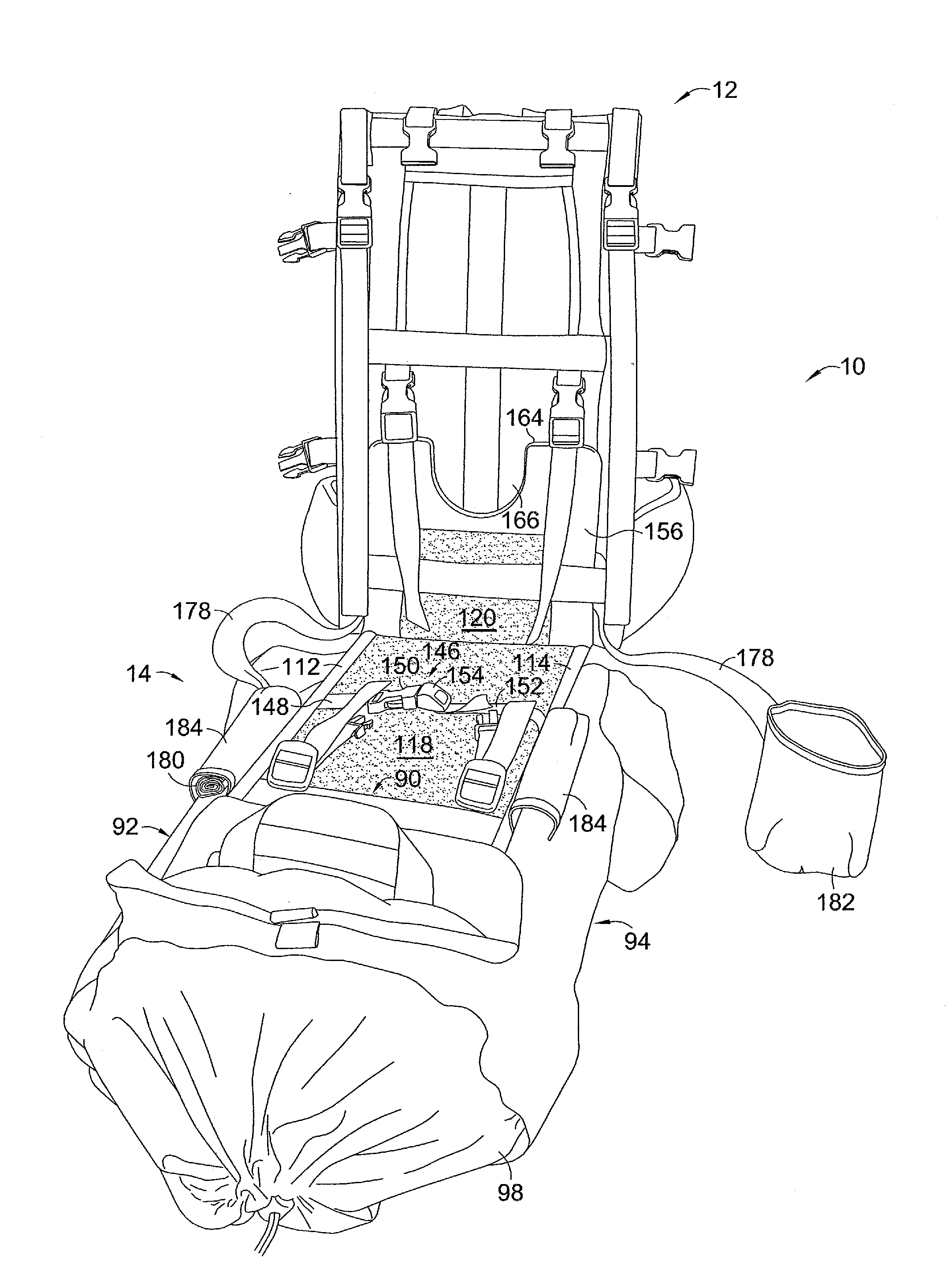
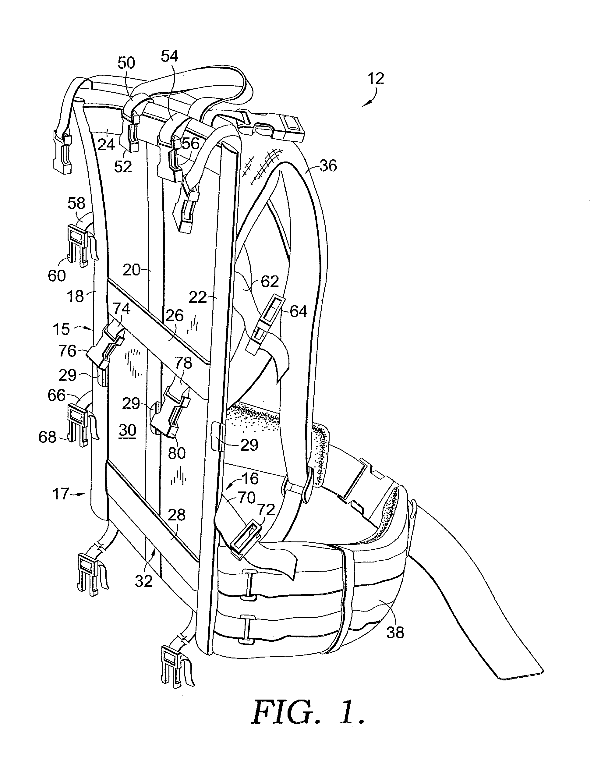
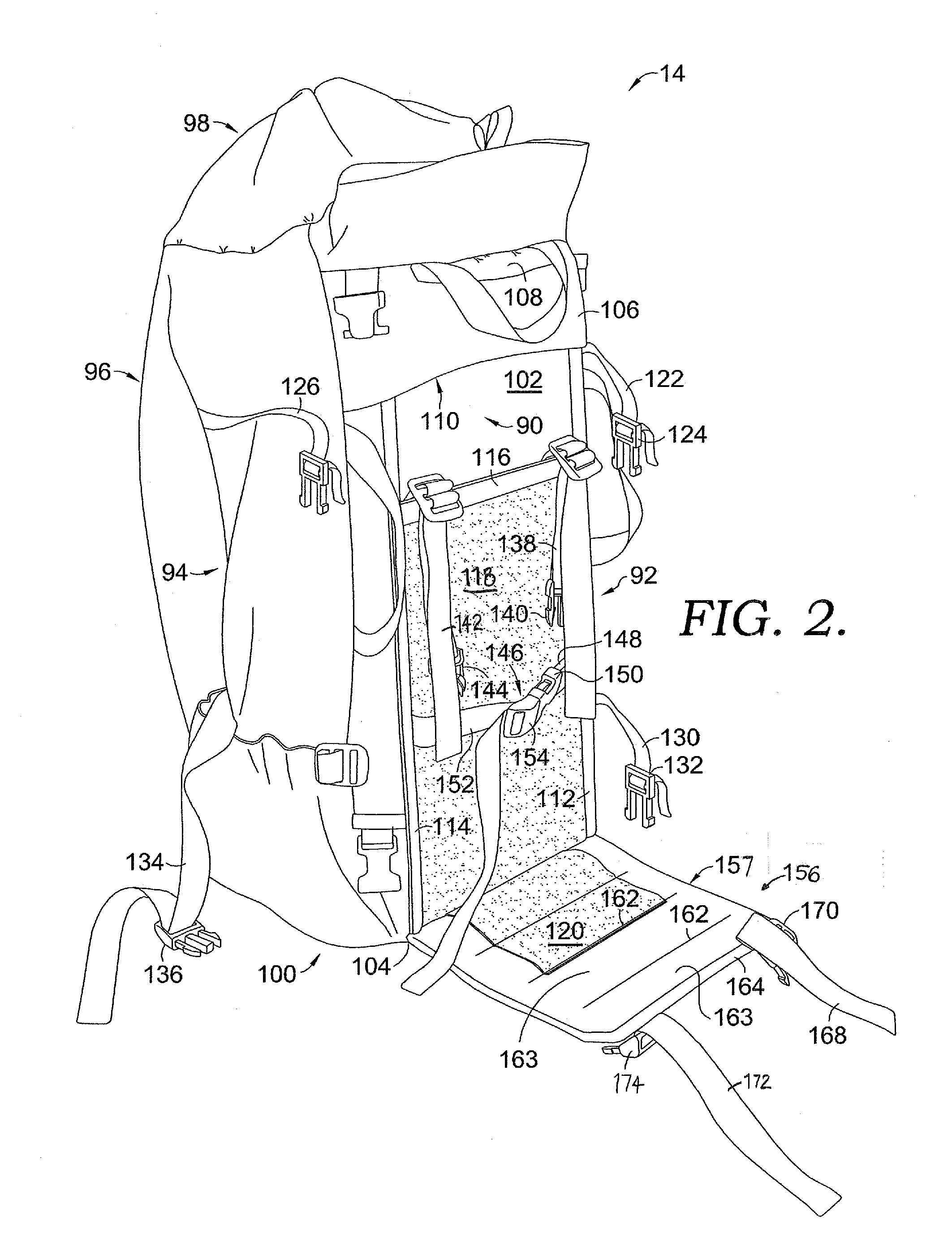
[0018]One embodiment of the present invention is directed generally to a backpack system 10 comprised of a frame system 12 and pack bag 14. As will be described in further detail below, the pack bag 14 may be mounted to the frame system 12 in a manner providing space 176 between the pack bag 14 and frame system 12 for accommodating cargo, including heavy, oversized or awkwardly shaped objects, therebetween. When configured in this manner, the b...


PUM


Abstract

A backpack system is provided including an external frame, a pack bag and a sling configured for extending between the frame and pack bag providing a space between the frame and pack bag for accommodating heavy or bulky cargo therebetween. The sling can be extended or retracted in order to selectively adjust the distance between the pack bag and frame. The backpack system may also include a pouch for supporting a lower end of relatively long object therein, which may be carried in the space between the pack bag and frame. In one embodiment, the pack bag is equipped with stiffening members for supporting the pack bag when not mounted directly to the frame.

Description

CROSS-REFERENCE TO RELATED APPLICATIONS[0001]This application is a continuation-in-part of and claims priority to U.S. application Ser. No. 10 / 907,087 filed Mar. 18, 2005 to Dana Wright Gleason Jr. entitled Backpack Frame System and U.S. application Ser. No. 12 / 533,983 filed Jul. 31, 2009 to Dana Wright Gleason Jr. entitled backpack Frame System, which is a continuation-in-part of U.S. application Ser. No. 10 / 907,087, both of which are currently pending. The entire disclosure, including the specification and drawings, of both above-referenced applications are incorporated herein by reference.BACKGROUND OF THE INVENTION[0002]Backpacks have been used for many years to carry a given load of contents on the back of a user. Modern backpacks designed and configured to carry moderate to large loads usually fall into one of two categories: external frame backpacks and internal frame backpacks. External frame backpacks normally include a rigid frame with shoulder straps and a pack bag connec...

Claims


Application Information

Patent Timeline
Patent Type & Authority Applications(United States)
IPC IPC(8): A45F3/00A45F3/04
CPCA45F3/08A45F3/10A45F3/06A45F3/04A45F2003/122
Inventor GLEASON, JR., DANA W.
Owner MYSTERY RANCH
Why Eureka
Try Eureka