Anatomical, pressure-evenizing mattress overlay

anatomical and pressure-evening technology, applied in the field of anatomical and pressure-evening mattress overlay, can solve the problems of real prevention and effective real prevention, and the cost of a mattress has been almost prohibitively high, and none of the results seem particularly successful or satisfactory, and achieve the effect of effective ventilation

Inactive Publication Date: 2010-07-29
MJD INNOVATIONS
View PDF23 Cites 9 Cited by
  • Summary
  • Abstract
  • Description
  • Claims
  • Application Information

AI Technical Summary

Benefits of technology

[0012]While there are probably many issues that are usefully addressable in terms of preventing decubitus ulcers, the three, key considerations which we specially recognize in the methodology and structure of the present invention involve: (a) (1) avoiding even very short-term (minutes) of high applied anatomical pressure, (2) at all times pressure-evenizing the contact-loading characteristics which define how the anatomy of a bed-ridden patient is supported, and (3) specifically producing a loading condition, static and dynamic, whereby there exist substantially no notably high-pressure points (preferably none exceeding about 32-mm Hg, and even more preferably not exceeding about 20-mm Hg), and definitively no conditions involving a projecting portion of the person's anatomy (i.e., a protuberance) bottoming out against either a non-yielding, or relatively non-yielding, underlying support surface, or in any manner significantly raising (de-evenizing) anatomical support pressure; (b) dealing effectively with the handling (removing) of moisture which may develop in the contact interface between a person's anatomy and the underlying support structure, and (c), very importantly, providing effective, ventilating airflow (more broadly, gas flow) in the region immediately beneath the contact supported anatomy so as to avoid the development of hot-spots and overheating, and especially recognizing that those portion of a supported anatomy, such as bony prominences, which create notable, downward “indentations” in an underlying support structure should be offered proportionally larger access to air (gas) flow.

Problems solved by technology

This “negative attention” has translated itself, among other things, into agency refusals to offer / provide relevant insurance coverage.
While the just-mentioned term “quite possible” is indeed true, real prevention—that is, effective real prevention—heretofore has been almost prohibitively expensive because of the fact that such prevention has, in reality, required substantial, frequent, personnel-intensive, one-to-one, or more-to-one, personal attendance to the changing of the resting “positions” of “bed-ridden” persons at risk.
In practice, none appears to be particularly successful or satisfactory, owing, as we perceive it, to the significant and apparent failure to grasp a full understanding of the body-support environmental contact conditions which must exist if decubitus “onset” is to be avoided.
While these prior-art approaches address, and attempt to tackle with resolution, certain technical medical issues and conditions that can lead to the development of decubitus injury (we will hereinafter use for such an injury the term “decubitus ulcer”), clearly taking aim, in the bargain, so to speak, at successfully minimizing costly medical-personnel attention to at-risk individuals, and repeating with emphasis what we have said above, as far as we can tell, no one has successfully developed a truly effective support structure and / or methodology which has(have) the capabilities of substantially eliminating, in most instances, the likelihood that such a decubitus ulcer will develop.
Unfortunately, known and proposed prior art manners of attacking the decubitus-ulcer problem do not recognize this special, anatomical-protuberance-support observation of ours, and failing that observation, actually propose supposedly problem-resolving body-support structures and associated methodologies which exacerbate the airflow problem associated with protuberance support by reacting to downward protuberances with either no attention paid to airflow, or even worse, increased constriction to airflow.

Method used


Image

  • Anatomical, pressure-evenizing mattress overlay
  • Anatomical, pressure-evenizing mattress overlay
  • Anatomical, pressure-evenizing mattress overlay

Examples


Embodiment Construction

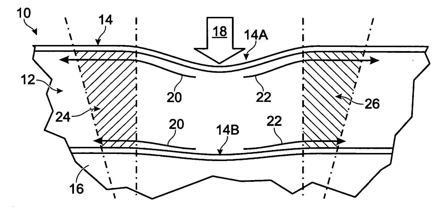
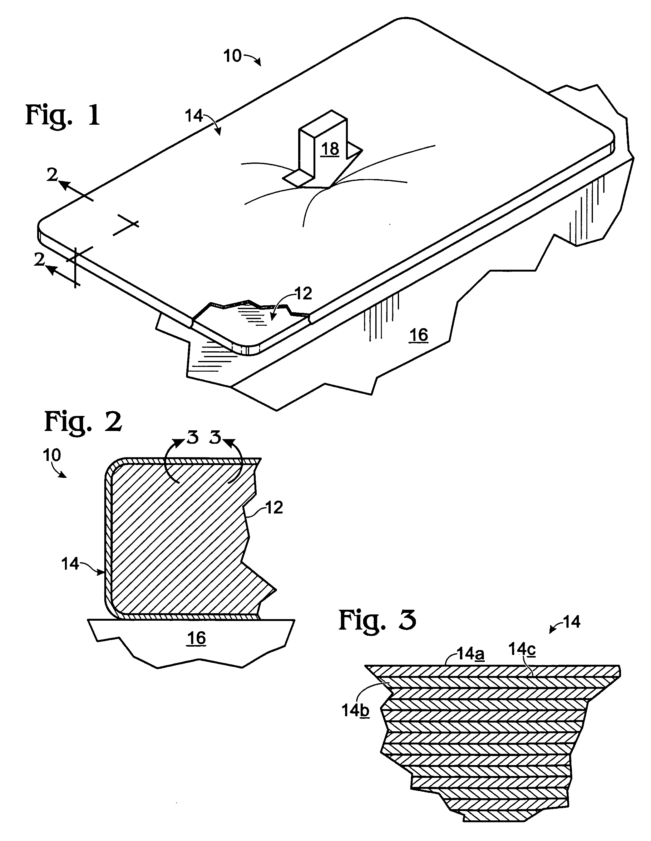
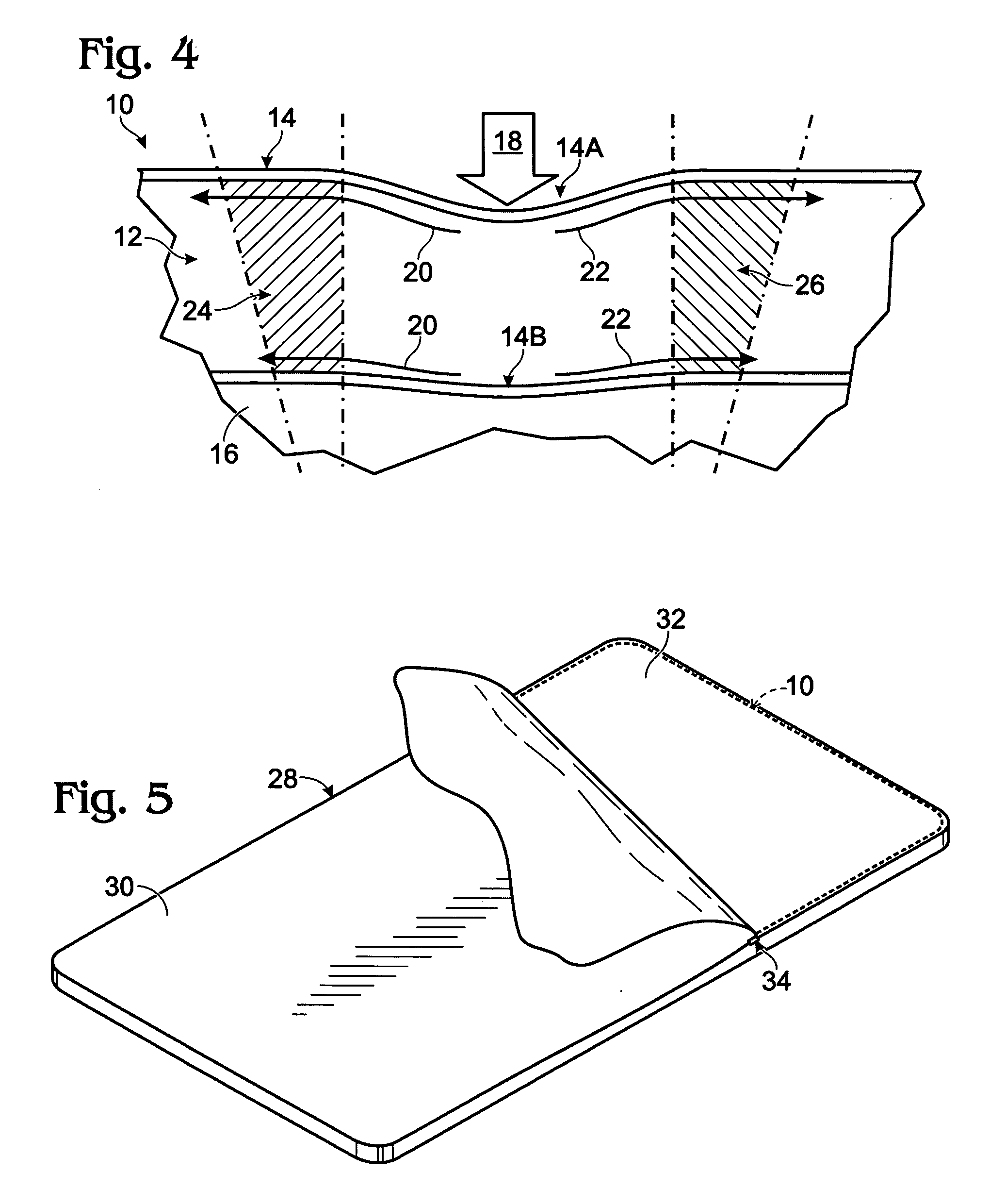
[0027]Turning attention now to the drawings, and referring first of all to FIGS. 1-3, inclusive, indicated generally at 10 is a preferred and best-mode embodiment of an anatomical, pressure-evenizing mattress overlay constructed in accordance with the present invention. Overlay 10 herein has an overall thickness of about 1-inches (a preferred maximum thickness), a lateral width of about 36-inches, and a length of about 75-inches. Overlay 10 is formed, basically, from two different components, or portions, including a single-piece, dynamic-response core expanse 12, and an elastomeric, air-breathable, moisture-resistant coating 14 which, as will shortly be explained, is load-transmissively (mechanically), interfacially (face-to-face) bonded to the entirety of the outside broad-planar and edge surface area of expanse 12.

[0028]In FIGS. 1 and 2, overlay 10 is shown resting upon a hospital-bed mattress of conventional construction shown generally and fragmentarily only at 16 in these two ...


PUM


Abstract

A method and structure for furnishing pressure-evenized, dynamic-reaction anatomical support. The method includes (a) supporting the anatomy with a 100% open cell viscoelastic foam, and (b) thereafter, and within the foam, reacting to both static and dynamic, anatomically-produced foam indentations to expand and contract cell-openness size, whereby deeper/sharper indentations result in greater-size cell-openness. Such reacting includes laterally stretching and flowing regions of the foam adjacent such an indentation The overlay structure features (1) a dynamic-response core expanse formed of a 100% open-cell, compressible and flowable, polyurethane, viscoelastic foam possessing a compressed, relaxed-state volume and (2) an elastomeric, moisture-resistant coating, load-transmissively, interfacially bonded to the entirety of the outside surface of the core expanse to function as a dynamically-responsive unit with the expanse. The coating possesses a relaxed-state prestressed tension condition which is responsible for the expanse's compressed condition.

Description

CROSS REFERENCE TO RELATED APPLICATION[0001]This application claims filing-date priority to prior-filed, currently copending U.S. Provisional Patent Application Ser. No. 61 / 206,126, filed Jan. 28, 2009, for “Anti-Decubitus-Injury Mattress Overlay”. The entire disclosure content of this prior-filed application is hereby incorporated herein by reference.BACKGROUND AND SUMMARY OF THE INVENTION[0002]The present invention pertains to a special-purpose, special-capability, breathable, moisture-controlling, anatomical-support, pressure-evenizing, “mattress overlay” intended to be placed on top of, and used in conjunction with, an underlying, yieldable support surface, such as that provided by a mattress, for the purpose of furnishing “direct”, pressure-evenizing under-support for a substantially bed-ridden person. It is specifically designed, as will be explained more fully below, with a thinness suitable, with appropriate, yieldable under-support, for handling persons weighing up to about...

Claims


Application Information

Patent Timeline
Patent Type & Authority Applications(United States)
IPC IPC(8): A47C27/14A47C21/00
CPCA47C27/006A47C27/14
Inventor DENNIS, CASEY A.DENNIS, MICHAEL R.
Owner MJD INNOVATIONS
Why Eureka
Try Eureka