Fixator

a fixator and non-invasive technology, applied in the field of non-invasive external fixators, can solve the problems of poor healing, soft tissue or bone, and increased risk of complications, and achieve the effects of time-consuming, uncomfortable, and convenient application for patients

Active Publication Date: 2016-04-26
CAMBRIDGE ORTHOPAEDIC LABS LTD
View PDF47 Cites 0 Cited by
  • Summary
  • Abstract
  • Description
  • Claims
  • Application Information

AI Technical Summary

Benefits of technology

[0021]Thus, during assembly of the bracelet about a patient's limb for example, the elements can be linked in an articulated relationship to facilitate correct sizing. Once appropriately assembled, the elements can be fixed to provide support for the limb during the healing process. The bracelet can therefore be made to fit snugly around the patient's limb by adjusting its length and curvature in the process of fitting, without the need for straps or other encircling bands. The bracelets can be made substantially rigid by simple application of digital pressure on the built-in locking mechanism that involves engaging the elements of the bracelet. Stability is provided by virtue of using a plurality of rows of elements that can be made substantially rigid when conforming in appropriate shape around the limb. Thus, the bracelet according to the invention is capable of changing from a substantially rigid and fixed state to a flexible and articulated state. The bracelet and its elements can be manipulated to conform to the desired shape (circular, oval, etc) and length.
[0065]The fixator preferably does not comprise any resilient materials (springs and the like). The hinge member articulates at the level of the joint line and at the level of the fracture. The ability to articulate at the two levels enables the device to reduce fracture fragments and mobilise the wrist. The device thus permits movement of a joint near the fracture site and also allows for fracture pieces to be manipulated and reduced in position and yet allows mobilisation in the joint plane. Therefore, the device aids fracture manipulation whilst allowing the patient to move the joint. In one embodiment, the fixator is for treating long bone factures.

Problems solved by technology

If this is not done, problems such as misalignment or poor healing can occur.
This invasive technique involves surgery, and as such there is a risk of infection of the soft tissue or bone, and further there is a risk of complications arising from the surgery.
A further disadvantage of conventional external fixators is where the fixator spans a joint, such as the wrist or ankle.
Articulated fixators are known, but these have disadvantages as well.
Alignment of the articulation with the joint can be difficult if not impossible, due to articulation of the fixator not being in the plane of the joint line axis.
Known devices do not allow movement in the joint's plane of motion.
Furthermore, known articulated fixators also have the disadvantage that if the fractured joints are moved in fracture situation, this will disturb the fracture position.
Furthermore, as with other known devices, the device in U.S. Pat. No. 4,677,971 is not suitable for treating long bone fractures because the articulation piece is not at the fracture site or joint level and does not allow movement in the joint plane.
In certain locations, such as for a fracture of the radial bone, the patient's thumb may prevent suitable alignment of the steel rod and the articulation.
However, such fixators necessitate a number of invasive pin placements and lead to a very big and cumbersome fixator.
However, these hinges have limitations to be used in fracture fixation device.
It is very difficult to assess the centre of rotation of these hinges on radiographs and to ascertain whether these are in the plane of the joint motion.

Method used


Image

  • Fixator
  • Fixator
  • Fixator

Examples


Embodiment Construction

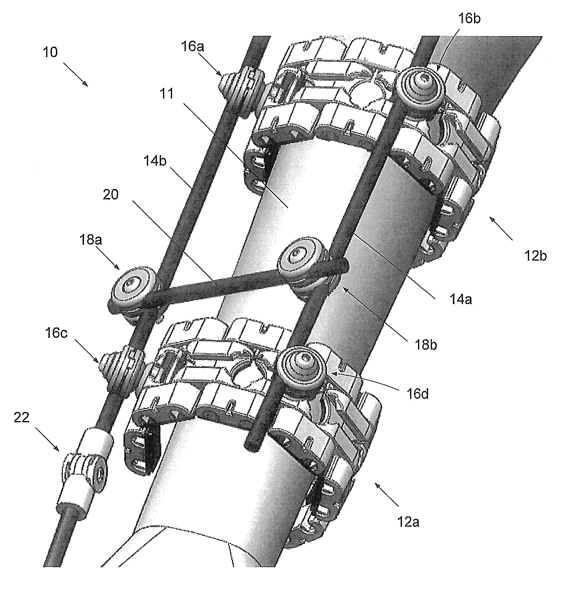
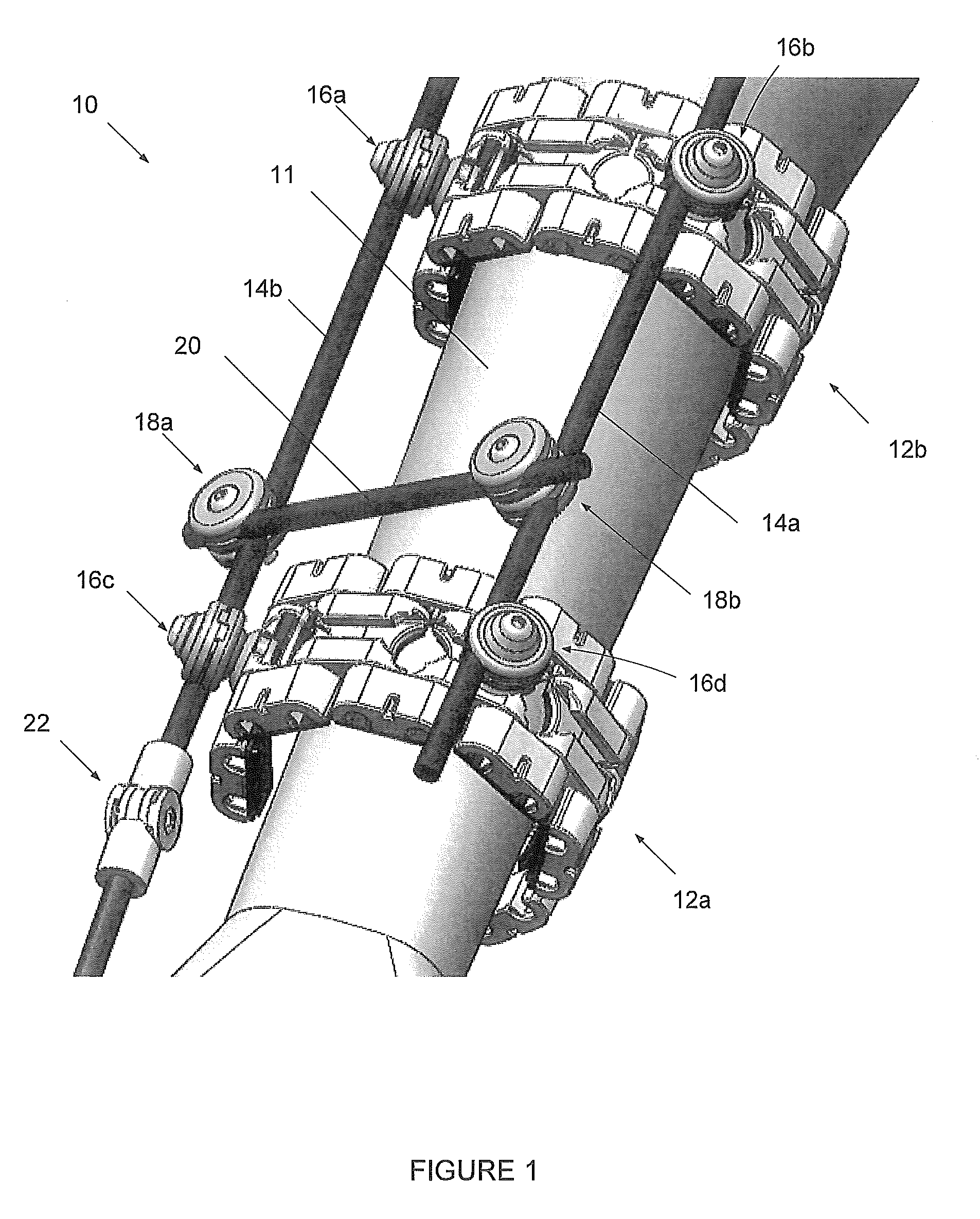
[0080]FIG. 1 shows a non-invasive fixator 10 according to the present invention, mounted on an arm 11 of a patient. The fixator 10 comprises two bracelets 12a, 12b that are maintained in relative positions on the arm by two approximately parallel running rods 14a, 14b, which are secured to the bracelets by means of four connecting devices 16a, 16b, 16c, 16d (two at each bracelet). A third rod 20 is secured crosswise by two cross-linking devices 18a, 18b. A hinging device 22 is connected at one end of rod 14b. The hinge device is connected by means of a rod to another bracelet or a cuff (not shown). Thus, in a preferred embodiment, the fixator comprises three bracelets. The hinge device is aligned with the plane of the joint, adjacent to fracture zone, movement.

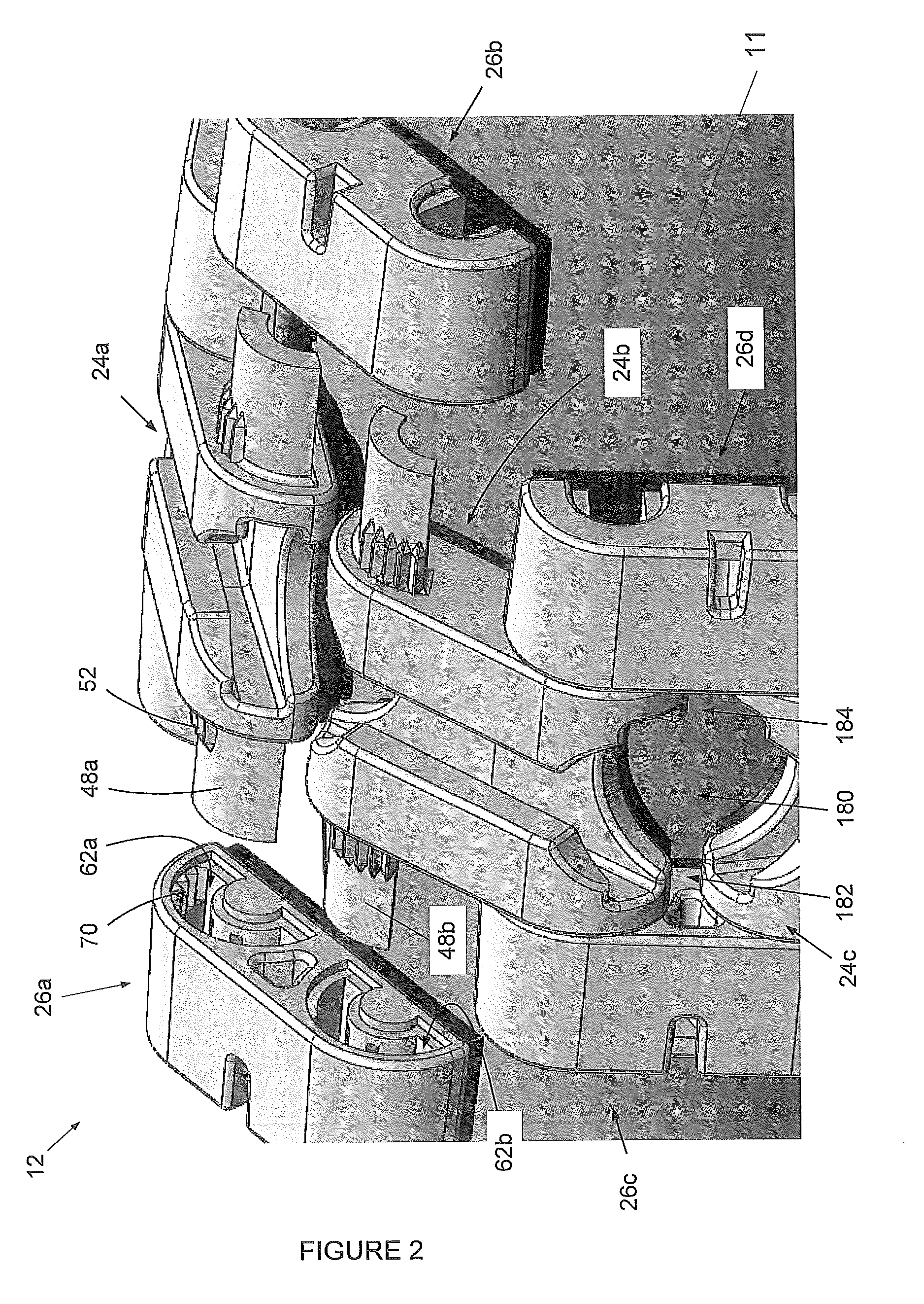
[0081]The bracelets 12 are comprised of a plurality of elements arranged in rows. In the exemplary configuration shown in FIG. 1, the elements are arranged in three rows: a central row and two outer rows. This is illustrated i...


PUM


Abstract

We describe fixator (10) comprising an articulated bracelet (12). The bracele comprises a plurality of elements (24,26) arranged in a plurality of rows. The elements have complementary linking means (48,62) to permit linking the rows of elements together in an articulated or fixed relationship. One or more of the plurality of elements comprises means (34) for receiving and engaging at least a portion of a connecting device (16) such that the position of the connecting device can be altered around the bracelet or the limb that it is mounted on. The fixator further comprises an articulated connecting device, a rod and a hinge device.

Description

FIELD OF THE INVENTION[0001]The present invention relates to a non-invasive external fixator particularly suitable for fracture fixation. Particular embodiments of the invention relate to an external fixator which allows for movement in a joint adjacent a fracture site; while certain embodiments relate to a fixator useful in movement, distraction and / or reduction of a fracture.BACKGROUND OF THE INVENTION[0002]When a bone is fractured, it is often necessary to hold the fragments of the bone together to allow for correct healing. If this is not done, problems such as misalignment or poor healing can occur.[0003]A conventional means for fixing fracture fragments is an external fixator, which typically takes the form of a steel or other material rod spanning across the fracture which is fixed to the bone fragments using pins. The rod is located outside the body, while the pins penetrate the skin and are fixed in the bone. This invasive technique involves surgery, and as such there is a ...

Claims


Application Information

Patent Timeline
Patent Type & Authority Patents(United States)
IPC IPC(8): A61F13/00A61B17/17A61F5/042A61F5/048A61F5/01A61F5/37A61F5/00A61F5/04A61B17/56A61B17/00A61F4/00A61B17/68A61F2/30A61F2/46A61F2/00A61B17/70A61F5/058
CPCA61F5/042A61F5/05866A61F5/00A61F5/01A61B17/1764A61F5/04A61B17/1739A61F5/048A61F5/0125A61F5/0102A61B17/00A61B17/171A61F5/058A61B17/17A61B17/6408A61F5/013
Inventor ALI, BAJWAPOMEROY, LINDA
Owner CAMBRIDGE ORTHOPAEDIC LABS LTD
Why Eureka
Try Eureka