

Ice skate blade bending apparatus
a technology of bending blades and blades, which is applied in the direction of sport apparatus, skates, skating parts, etc., can solve the problems of bending blades in the blade section, little predictability in the process, and hesitant skaters to skate on blades ben
- Summary
- Abstract
- Description
- Claims
- Application Information
AI Technical Summary
Benefits of technology
Problems solved by technology
Method used
Image

Examples
Embodiment Construction
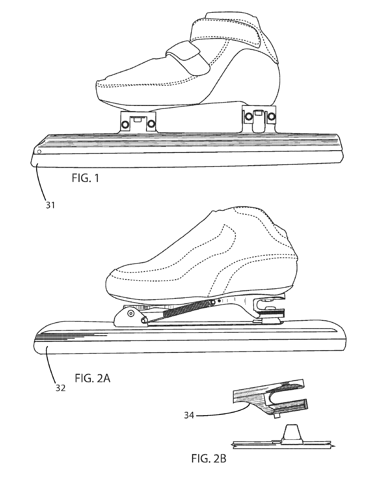
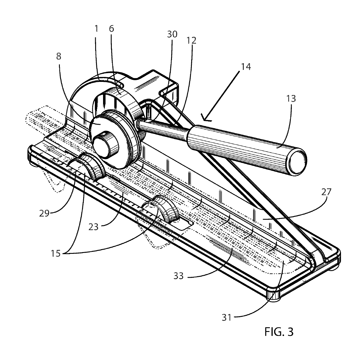
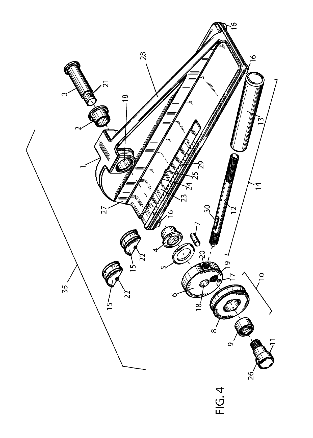
[0013]An embodiment of a skate blade bending apparatus for bending a skate blade is presented herein. A skate blade, having a generally elongated configuration, is defined as a blade runner which provides a contacting section for contacting a gliding surface such as ice, and a blade attachment section for attaching the blade to a skate boot. The skate blade also defines a blade longitudinal axis, a blade first side surface, and a blade second side surface. The bending apparatus is comprised of: a one-piece frame; a pressure exerting means attached to the frame for exerting bending pressure on a skate blade in a pressure direction generally perpendicular to the blades longitudinal axis at a predetermined pressure location; an integrated shape within the frame design which allows the user to more precisely apply force to the pressure exerting means, and a blade securing means attached to the frame for locally securing the skate blade so as to allow the bending pressure exerted by the ...
PUM
| Property | Measurement | Unit |
|---|---|---|
| bending pressure | aaaaa | aaaaa |
| force | aaaaa | aaaaa |
| mechanical advantage | aaaaa | aaaaa |
Abstract
Description
Claims
Application Information