
Auxiliary thumbnail and piston ring removal and installation tool

A thumb and nail technology, applied in the field of auxiliary thumb nails and piston ring disassembly and assembly tools, can solve the problems of thumb nail damage, separation of fingers, painful thumb nail pulling force, etc., to achieve the effect of improving efficiency and improving force

Pending Publication Date: 2019-07-26
SHANDONG JIAOTONG UNIV
View PDF0 Cites 0 Cited by
  • Summary
  • Abstract
  • Description
  • Claims
  • Application Information

AI Technical Summary

Problems solved by technology

[0004] In view of the above-mentioned defects of the prior art, the technical problem to be solved by the present invention is to solve the situation where the thumbnail is frequently used for pulling and pulling, which may easily cause damage to the thumbnail, separation of the thumbnail and the thumb, resulting in finger pain and insufficient pulling force of the thumbnail. problems, especially to solve the problem of inconvenient disassembly and assembly of piston rings in engine maintenance

Method used


Image

  • Auxiliary thumbnail and piston ring removal and installation tool
  • Auxiliary thumbnail and piston ring removal and installation tool
  • Auxiliary thumbnail and piston ring removal and installation tool

Examples


Embodiment 1

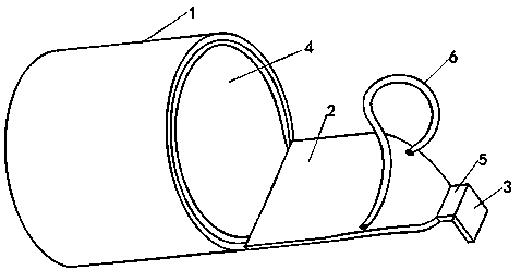
[0057] Such as figure 1 Shown is a schematic view of the structure of the auxiliary thumb nail in a preferred embodiment of the present invention. The auxiliary thumbnail of the present embodiment includes a thumb clamping surface 1, a force application surface 2 and a working surface 3, and lining materials 4 such as rubber, silica gel or cloth, fiber materials, etc. Positioning surfaces 5 are provided at both ends, and an elastic retaining belt 6 is provided on the force application surface 2 .

[0058] The thumb clamping surface 1 is a cylindrical surface with a length of 2.1 cm; the first end of the thumb clamping surface 1 is at the mouth of the tiger, and the second end of the thumb clamping surface 1 does not go beyond the first and second joints of the thumb joint; the inner diameter of the thumb clamping surface 1 is 2.6 centimeters. The thumb locking surface 1 is set on the thumb. When the thumb is bent, the center line of the thumb locking surface 1 deviates from ...

Embodiment 2

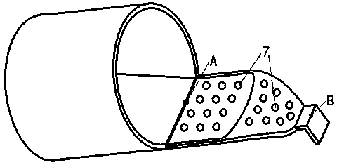
[0067] figure 2 It is a schematic diagram of the arrangement of anti-slip bosses on the force application surface of a preferred embodiment of the present invention. The anti-slip boss 7 in this embodiment is an anti-slip measure for the force-applying surface 2 to ensure the force applied by the thumb. The force application surface 2 is an important part of the force application by the thumb, which mainly relies on positive pressure and friction to generate pulling force. The anti-skid boss 7 is set on the force application surface 2 to prevent slippage between the thumb and the force application surface 2, increase the friction force, properly reduce the positive pressure, reduce the force of the two ends of the thumb clamping surface 1, and improve the stability of the working process. comfort. In addition, the anti-slip boss 7 can increase the roughness of the contact surface, thereby increasing the friction between the thumb and the force application surface 2 . Durin...

Embodiment 3

[0070] Figure 4 It is a schematic diagram of the bolt connection joint between the force application surface and the thumb clamping surface in a preferred embodiment of the present invention. The thumb clamping surface 1 and the force application surface 2 are manufactured separately, and are fixed into one body through a bolt connection joint 9 . The bolted joint 9 is a high-strength connection. Wherein, the thumb locking surface 1 and the force application surface 2 are made of different materials, the force application surface 2 is made of a material with higher rigidity, and the thumb locking surface 1 is made of a soft material. Adopting the bolt connection joint 9 can make the thumb locking surface 1 and the force application surface 2 be assembled and connected, which is convenient for manufacture and disassembly. It can not only ensure that the auxiliary thumb has greater rigidity and strength, avoid excessive deformation, but also make the thumb touch the soft mate...


PUM


Abstract

The invention discloses an auxiliary thumbnail and a piston ring removal and installation tool. The auxiliary thumbnail is composed of a thumb clamping face, a force application face and a working face; the thumb clamping face is a barrel face; the second end of the thumb clamping face is fixedly connected with the first end of the force application face; the second end of the force application face is fixedly connected with the first end of the working face; a specific angle is formed between the working face and the axis of the thumb clamping face; the distance between the first end of the working face and the first end of the force application face is a specific value; and the distance between the first end of the working face and the center line of the thumb clamping face is a specificvalue. The invention provides a flexible manual scraping tool, and damage due to direct force application by finger nails is avoided; force is applied by pressing through a thumb, and the scraping force is increased; the scraping process can be located more accurately, and the force application is accurate; and the auxiliary thumbnail is flexible and convenient. The invention provides a piston ring removal and installation tool composed of two auxiliary thumbnails, and the tool can be used for removal and installation of piston rings in various diameters which are smaller than 120 mm; and theremoval and installation efficiency of the piston ring is improved.

Description

technical field [0001] The invention relates to the field of internal combustion engine maintenance, in particular to an auxiliary thumbnail and piston ring disassembly tool. Background technique [0002] During engine maintenance, disassembling piston rings is a common maintenance content. At present, piston ring disassembly and assembly pliers are usually used to disassemble and assemble piston rings. The piston ring at the three fulcrum flat ends of the piston ring dismounting pliers is used for disassembly and assembly, and there is a problem of unstable lifting of the piston ring, and the tension force of the piston ring disassembly is opened by the opening of the piston ring dismounting pliers, and the strength is not enough. It is easy to control and easy to break the piston ring, which requires high technical requirements for the piston ring loading and unloading personnel. On the other hand, piston ring dismounting pliers are only suitable for piston rings of a sp...

Claims


Application Information

Patent Timeline
IPC IPC(8): B25B27/20
CPCB25B27/20
Inventor 王传胜王希波李爱娟陈政宏
Owner SHANDONG JIAOTONG UNIV
Learn More