Ac - DC converter

a converter and ac technology, applied in the direction of electric variable regulation, process and machine control, instruments, etc., can solve the problems of disadvantageous defects of ac-dc converters, disadvantageous output voltages of ac-dc converters, and low output voltages, so as to improve input power factor, reduce power consumption, and curb fluctuation of output voltage

Active Publication Date: 2010-07-29
SANKEN ELECTRIC CO LTD
View PDF2 Cites 13 Cited by
  • Summary
  • Abstract
  • Description
  • Claims
  • Application Information

AI Technical Summary

Benefits of technology

[0014]The converter according to the present invention can curb fluctuation in output voltage from boosting chopper circuit under the wavering AC input voltage to improve input power factor from AC voltage, and therefore, it can control or inhibit power loss of main switching element in DC-DC converter without need of large-sized transformer, while reining voltage distortion and concomitant harmonic noise which may occur in AC power source. Moreover, power consumption can be reduced during light load period, disabling operation of boosting chopper circuit.

Problems solved by technology

However, prior art AC-DC converter shown in FIG. 6 disadvantageously has some defects because it needs to have complicated chopper control circuit 50 and large-sized reactor 4 to deliver a large amount of intensified current IQ1 through reactor 4 and boosting MOS-FET 5 turned on and off with concomitant power loss.
Accordingly, in response to fluctuation in input voltage from AC power source, boosting chopper circuit produces fluctuated output voltage so that AC-DC converter disadvantageously produces an unstable output voltage.
Widely fluctuating output voltages produced from boosting chopper circuit expands the control range of on-off period of first switching transistor in DC-DC converter by fluctuated component in output voltage of boosting chopper circuit while provoking an increased power loss by first switching transistor and a large-sized transformer.
Also, when boosting chopper circuit produces an output voltage lower than reference voltage within comparator under the light load condition, comparator produces an output signal which makes one-shot multi-vibrator stop producing relayed pulse, and generally simultaneously drives first and second switching transistors, and therefore, the converter still has a trouble because it increases power loss during light load period.

Method used


Image

  • Ac - DC converter
  • Ac - DC converter
  • Ac - DC converter

Examples


Embodiment Construction

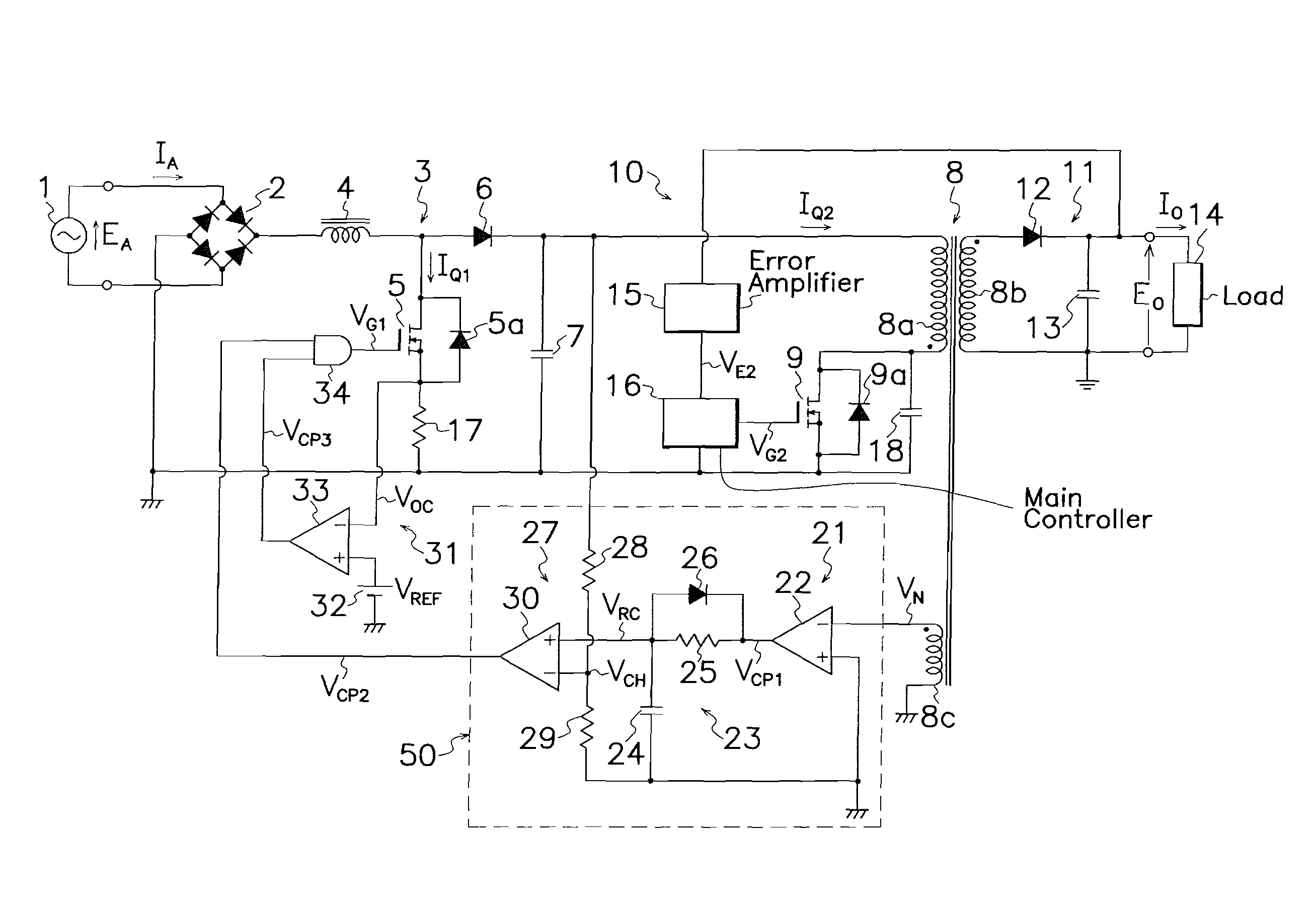
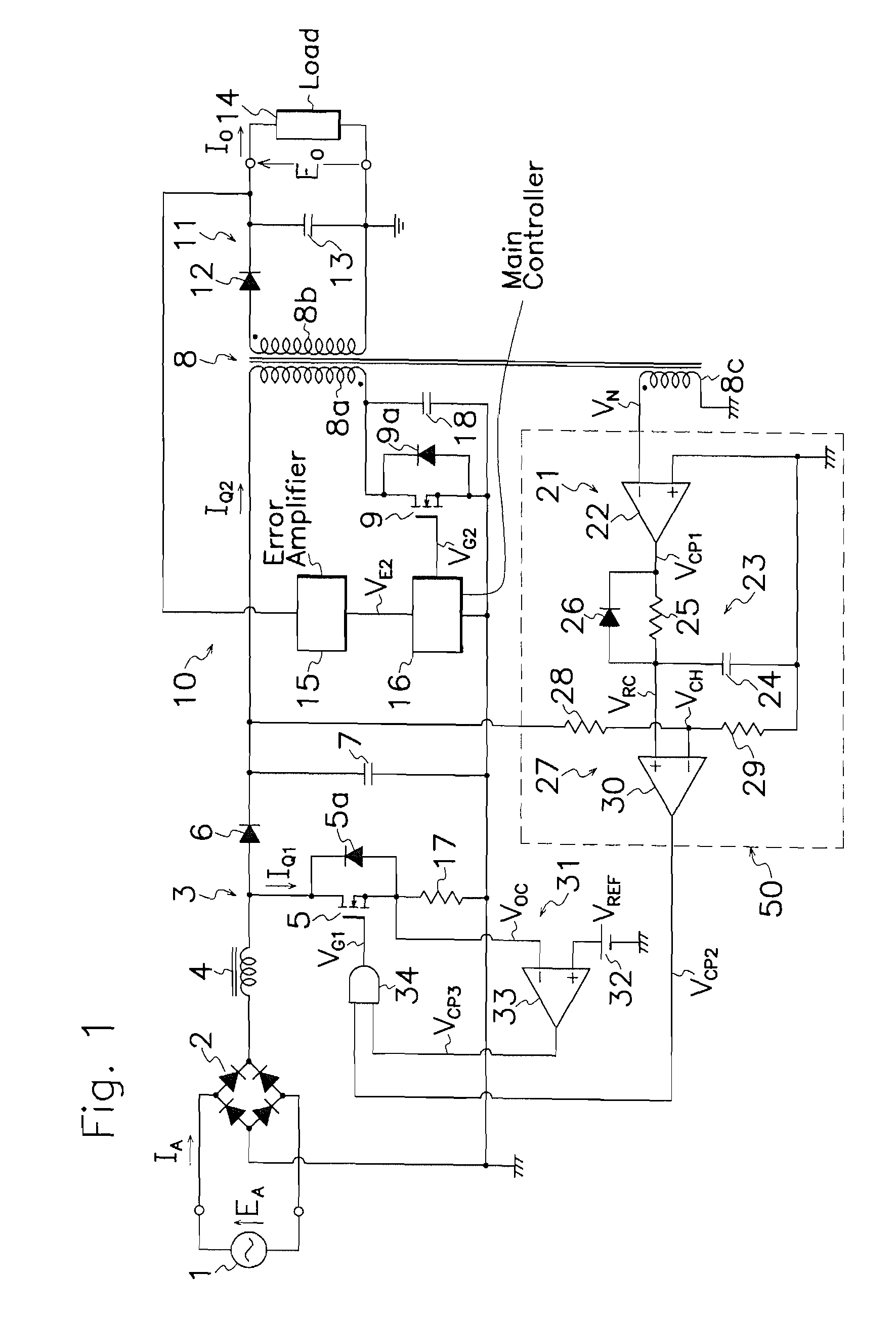
[0023]An embodiment of the AC-DC converter according to the present invention is described hereinafter with reference to FIGS. 1 to 5 of the drawings. Same symbols are applied to substantially same parts in FIGS. 1 to 5 as those shown in FIGS. 6 and 7, and their explanation is omitted.

[0024]As shown in FIG. 1, the AC-DC converter according to the present embodiment comprises an auxiliary winding 8c in electro-magnetic coupling with primary winding 8a of transformer 8 shown in FIG. 6 in the adverse polarity, and a chopper control circuit (chopper controller) 50 connected to auxiliary winding 8c. Chopper controller 50 comprises a winding voltage detecting circuit (winding voltage detector) 21 for detecting voltage VN appearing on auxiliary winding 8c by on-off operation of main MOS-FET 9 in DC-DC converter 10 to produce an output signal VCP1 of high voltage level when auxiliary winding 8c produces one-sided or negative voltage VN, a waveform shaper 23 for generating a linearly rising ...


PUM


Abstract

AC-DC converter is provided which comprises an auxiliary winding 8c in a transformer 8, a voltage detector 21 for detecting a voltage VN appearing on auxiliary winding 8c of transformer 8 by on-off operation of a main switching element 9 in a DC-DC converter 10 to produce an output signal VCP1 when voltage VN on auxiliary winding 8c has a negative polarity, a waveform shaper 23 for generating chopping signals VRC from output signal VCP1 of voltage detector 21, and a PWM circuit 27 for comparing output voltage VRC from waveform shaper 23 and output voltage VCH from a boosting chopper 3 to supply drive signals VG1 to step-up switching element 5 in boosting chopper 3 when output voltage VRC from waveform shaper 23 exceeds output voltage VCH from boosting chopper 3. While controlling fluctuation in output voltage from boosting chopper with respect to fluctuation in AC input voltage, the converter can improve input power factor relative to AC voltage and also reduce consumption power during light load period.

Description

TECHNICAL FIELD IN INDUSTRY[0001]This application is a U.S. national phase submission of Patent Cooperation Treaty PCT / JP2008 / 054467 under 35 U.S.C. 371 based on Japanese Patent Application No. 2007-157936 filed 14 Jun. 2007. This invention relates to an AC-DC converter of the type capable of improving the input power factor relative to AC voltage and also reducing the consumption power during light load period while controlling fluctuation in output voltage from a boosting chopper circuit under variation in AC input voltage.PRIOR ART[0002]AC-DC converters have been widely used in the past which comprises a rectification circuit for commutating AC voltage from an AC power source, a DC-DC converter for producing a DC voltage from an output voltage of the rectification circuit through a transformer and a rectification smoothing circuit by on-off operation of a switching element, and a boosting chopper circuit connected between the rectification circuit and DC-DC converter to improve i...

Claims


Application Information

Patent Timeline
Patent Type & Authority Applications(United States)
IPC IPC(8): H02M3/335
CPCH02M1/4225H02M3/33507Y02B70/16H02M2001/007Y02B70/126H02M2001/0032Y02B70/10H02M1/0032H02M1/007
Inventor SATO, MAKOTOSATO, MITSUTAKA
Owner SANKEN ELECTRIC CO LTD
Why Eureka
Try Eureka