A control method and device for a step-down circuit

A technology of step-down circuit and control method, applied in output power conversion devices, control/regulation systems, photovoltaic power generation, etc. Small voltage and power fluctuations, suppressing output voltage fluctuations, and ensuring stable transition effects

Active Publication Date: 2017-02-15
SUNGROW POWER SUPPLY CO LTD
View PDF5 Cites 0 Cited by
  • Summary
  • Abstract
  • Description
  • Claims
  • Application Information

AI Technical Summary

Problems solved by technology

However, in the prior art, when such a working state is switched, it is easy to cause voltage or power fluctuations on the input side
E.g figure 1 Among them, the switch tube S1, the diode D and the inductor L form a Buck circuit, and the switch tube S2 forms a bypass circuit. S2 is in the normally-on state. Since the output voltage of the DC power supply (that is, the voltage across capacitor C1) is usually higher than the bus voltage (that is, the voltage across capacitor C2), the instantaneous current flowing through the switch tube S2 is relatively large, which in turn leads to DC The output voltage of the power supply produces large fluctuations
When switching from the bypass circuit to the Buck circuit, controlling the switching tube S1 to be in the PWM working state while the switching tube S2 is in the off state will also cause the switching process to be unstable and cause output power fluctuations.

Method used


Image

  • A control method and device for a step-down circuit
  • A control method and device for a step-down circuit
  • A control method and device for a step-down circuit

Examples


Embodiment Construction

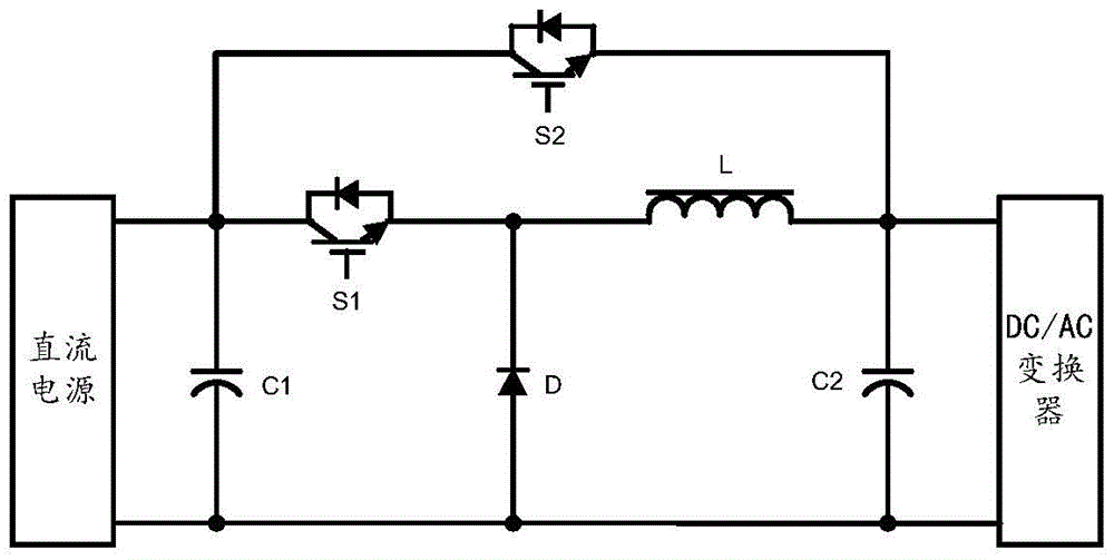
[0048] In the field of photovoltaic power generation, the grid-connected inverter usually adopts a two-stage structure of DC / DC converter and DC / AC converter, in which the DC / DC converter completes the conversion of DC voltage, and the DC / AC converter converts the DC / DC The DC output from the converter is converted to AC at the desired frequency. Among them, the DC / DC converter can adopt a step-up conversion circuit, a step-down conversion circuit, or a conversion circuit with both step-up and step-down functions. In order to improve efficiency, the DC / DC converter usually adopts a bypass structure, that is, Together with the bypass circuit connected in parallel, it forms a step-down circuit.

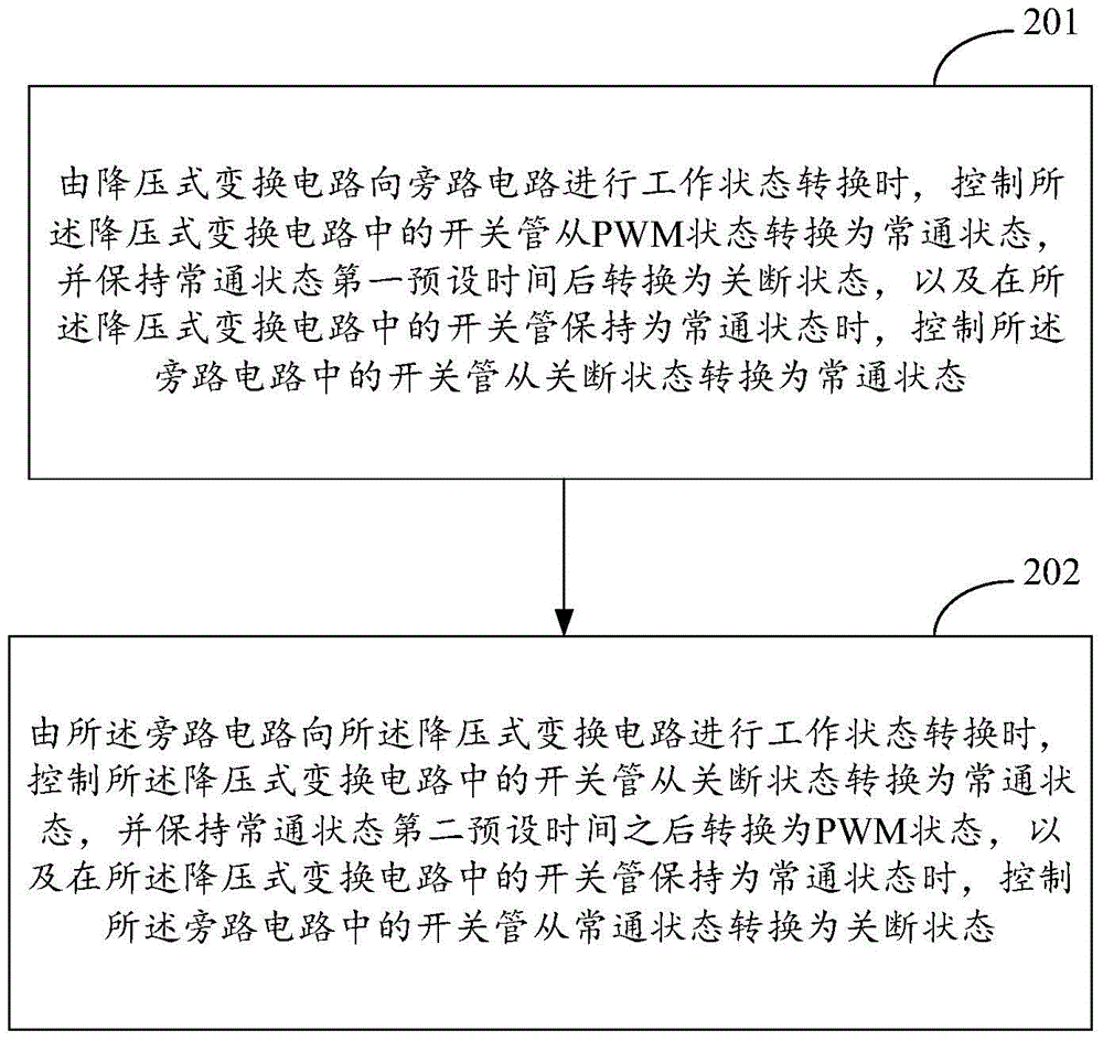
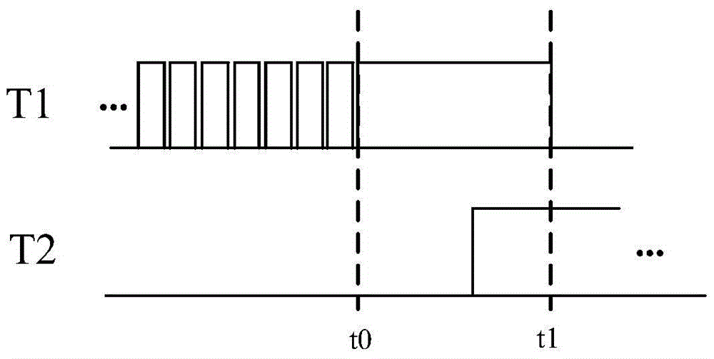
[0049] In the actual working process, the step-down conversion circuit and the bypass circuit will continuously switch working states according to actual needs. However, in the prior art, voltage or power fluctuations at the input side are easily caused when such a working state is swi...


PUM


Abstract

The invention provides a method and a device for controlling step-down circuits. The method includes converting states of switch tubes of step-down type conversion circuits into normally open states under the control when working state conversion is carried out on bypass circuits by the step-down type conversion circuits, keeping the switch tubes of the step-down type conversion circuits in the normally open states for first preset time, then converting the states of the switch tubes into shutdown states, and converting states of switch tubes of the bypass circuits into normally open states under the control when the switch tubes of the step-down type conversion circuits keep in the normally open states; converting the states of the switch tubes of the step-down type conversion circuits into the normally open states under the control when working state conversion is carried out on the step-down type conversion circuits by the bypass circuits, keeping the switch tubes of the step-down type conversion circuits in the normally open states for second preset time, then converting the states of the switch tubes of the step-down type conversion circuits into PWM (pulse width modulation) working states, and converting the states of the switch tubes of the bypass circuits into shutdown states under the control when the switch tubes of the step-down type conversion circuits keep in the normally open states. The method and the device have the advantage that working states can be converted between the step-down type conversion circuits and the bypass circuits by the aid of the method and the device under the condition of low voltage and power fluctuation.

Description

technical field [0001] The invention relates to the field of grid-connected inverters, in particular to a control method and device for a step-down circuit. Background technique [0002] In the field of photovoltaic power generation, the grid-connected inverter usually adopts a two-stage structure of DC / DC converter and DC / AC converter, in which the DC / DC converter completes the conversion of DC voltage, and the DC / AC converter converts the DC / DC The DC output from the converter is converted to AC at the desired frequency. Among them, the DC / DC converter can adopt a step-up conversion circuit, a step-down conversion circuit, or a conversion circuit with both step-up and step-down functions. In order to improve efficiency, the DC / DC converter usually adopts a bypass structure, that is, Together with the bypass circuit connected in parallel, it forms a step-down circuit. [0003] In the actual working process, the step-down conversion circuit and the bypass circuit will cont...

Claims


Application Information

Patent Timeline
Patent Type & Authority Patents(China)
IPC IPC(8): H02M3/155
CPCY02E10/56
Inventor 曹金虎李浩源伍永富王鹏梅白军廉磊
Owner SUNGROW POWER SUPPLY CO LTD
Why Eureka
Try Eureka