DC/DC converter

a converter and converter technology, applied in the direction of dc-dc conversion, power conversion systems, instruments, etc., can solve the problems of high duty ratio of each channel, poor stability of output voltage, and large amount of current, so as to suppress the fluctuation of output voltag

Active Publication Date: 2018-02-13
ROHM CO LTD
View PDF11 Cites 0 Cited by
  • Summary
  • Abstract
  • Description
  • Claims
  • Application Information

AI Technical Summary

Benefits of technology

[0013]The present invention has been made in order to solve such a problem. Accordingly, it is an exemplary purpose of an embodiment of the present invention to provide a multi-channel DC / DC converter and a control circuit for controlling the multi-channel DC / DC converter having an advantage of suppressing fluctuation of the output voltage VOUT involved in switching the number of enabled channels.
[0015]With such an embodiment, by correcting the duty ratio when the channel switching operation is performed, such an arrangement is capable of suppressing fluctuation of the output voltage, i.e., suppressing overshoot and undershoot in the output voltage.
[0016]Also, the soft shedding circuit may be structured to superimpose the corresponding correction signal on the error signal side input for each correction target channel. This provides improved stability of the output voltage without damaging the circuit stability.
[0017]Also, the soft shedding circuit may be structured such that, when the number of enabled channels is reduced, the correction signal is superimposed on the channels to be disabled after the channel switching, with a duty ratio that drops with time. This suppresses undershoot.
[0018]Also, the soft shedding circuit may be structured such that, when the number of enabled channels is increased, the correction signal is superimposed on the channels to be newly enabled, with a duty ratio that rises from zero. This suppresses overshoot.
[0020]This suppresses fluctuation of the output voltage while maintaining the current balance between channels.

Problems solved by technology

However, as a result of investigating such hard shedding, the present inventor has recognized that hard shedding has a problem of poor stability of the output voltage VOUT as described below.
This leads to a problem of supplying an amount of current larger than the ideal amount of current.
That is to say, when the load current ILOAD increases, the duty ratio of each channel becomes excessive.
This leads to the generation of a surplus amount of coil current, leading to overshoot in the output voltage VOUT.
Conversely, when the load current ILOAD decreases, the duty ratio of each channel becomes too small.
This leads to the generation of an insufficient amount of coil current, leading to undershoot in the output voltage VOUT.
Such problems are not restricted to such a step-up DC / DC converter, but can occur in various kinds of converters such as step-down (Buck) DC / DC converters, step-up / step-down converters, etc.

Method used


Image

  • DC/DC converter
  • DC/DC converter
  • DC/DC converter

Examples


first modification

[First Modification]

[0122]The current balance circuit 220a shown in FIG. 10 may include an averaging circuit that generates an average value of the current detection signals VIS instead of the sample-and-hold circuits 222. Such an averaging circuit may be configured as a low-pass filter.

second modification

[Second Modification]

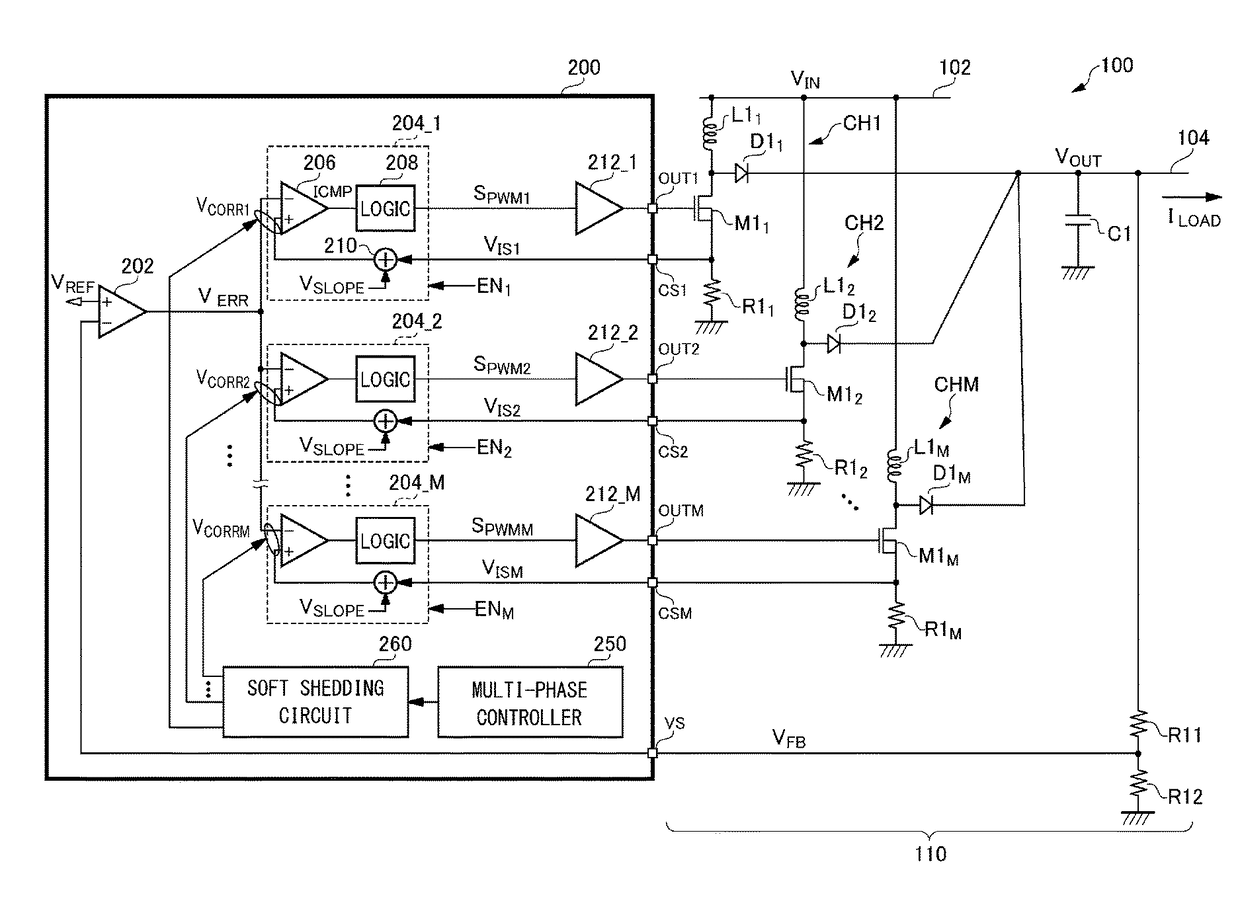
[0123]Description has been made in the embodiment regarding a diode rectification DC / DC converter. Also, the present invention is applicable to a synchronous rectification DC / DC converter. Also, the present invention is applicable to a step-down DC / DC converter and a step-up / step-down DC / DC converter. In this case, the topology of the output circuit 110 shown in FIG. 3 may preferably be modified.

third modification

[Third Modification]

[0124]In FIG. 3, the detection method for detecting the coil current IL is not restricted in particular. For example, the on resistance of the switching transistor M1 may be used instead of the current sensing resistor R1. Also, an additional transistor may be provided as a replica of the switching transistor M1 such that a current flows through the replica transistor in proportion to the current that flows through the switching transistor M1. With such an arrangement, the current that flows through the replica transistor may be detected.


PUM


Abstract

An error amplifier amplifies a difference between a feedback signal VFB that corresponds to an output voltage VOUT of a DC / DC converter and its target value VREF, so as to generate an error signal VERR. A pulse width modulator for each channel is configured as a peak current mode modulator comprising a PWM comparator that compares a current detection signal VIS with the error signal VERR, and a logic circuit. When the number of enabled channels is switched, a soft shedding circuit selects at least one channel as a correction target channel. The soft shedding circuit generates a correction signal VCORR for each correction target channel, and superimposes each correction signal VCORR on at least one of two inputs of the corresponding PWM comparator.

Description

CROSS REFERENCE TO RELATED APPLICATIONS[0001]The present invention claims priority under 35 U.S.C. § 119 to Japanese Application No. 2016-012711, filed Jan. 26, 2016, the entire content of which is incorporated herein by reference.BACKGROUND OF THE INVENTION[0002]1. Field of the Invention[0003]The present invention relates to a DC / DC converter.[0004]2. Description of the Related Art[0005]Various kinds of electronic devices employ a DC / DC converter that converts a DC voltage having a given voltage value into a DC voltage having a different voltage value. In order to suppress ripple in the input current of the DC / DC converter, a multi-phase DC / DC converter is employed. FIG. 1 is a circuit diagram showing a multi-phase step-up (boost) DC / DC converter (which will simply be referred to as the “DC / DC converter”) 900. The DC / DC converter 900 receives a DC input voltage VIN via an input line 902, and generates a stepped-up voltage VOUT at an output line 904. The DC / DC converter 900 is confi...

Claims


Application Information

Patent Timeline
Patent Type & Authority Patents(United States)
IPC IPC(8): H02M3/155H02M1/084H02M3/157H02M3/158H02M1/14H02M1/36H02M1/00
CPCH02M3/157H02M1/084H02M1/36H02M1/14H02M2001/0009H02M3/1584H02M1/0009
Inventor TAKENAKA, SEIJI
Owner ROHM CO LTD
Why Eureka
Try Eureka