Illumination device and liquid crystal display device

Inactive Publication Date: 2010-09-09
SHARP KK
View PDF27 Cites 12 Cited by
  • Summary
  • Abstract
  • Description
  • Claims
  • Application Information

AI Technical Summary

Benefits of technology

[0019]In this regard, according to the arrangement of FIG. 13, light is emitted from an end surface (7e) of the second light guide (on the right side in FIG. 13), the end surface being opposite from a corresponding light source. The light then enters the first light guide (on the left side in FIG. 13) and is transmitted through it (indicated by arrows having bold solid lines in FIG. 13). The light is totally reflected in this first light guide and is then emitted from a light-emitting surface of the first light guide. The arrangement of FIG. 13 includes multiple light guides that together form a light-emitting surface having no gap as described above. This prevents occurrence of bright lines and thus allows for uniform luminance.
[0042]According to the above arrangement, the inclusion of one of the illumination devices of the present invention allows for production of a liquid crystal display device having superior luminance uniformity.

Problems solved by technology

However, in the illumination device configured by the combination of the light guides and the light sources as described above, aligning the plurality of light guides planerly poses such a problem that luminance still becomes non-uniform because of luminance unevenness caused by bright lines appearing in regions corresponding to joints between the light guides.

Method used


Image

  • Illumination device and liquid crystal display device
  • Illumination device and liquid crystal display device
  • Illumination device and liquid crystal display device

Examples


embodiment 2

[0104]A second embodiment of the present invention is described below with reference to FIGS. 5 through 12.

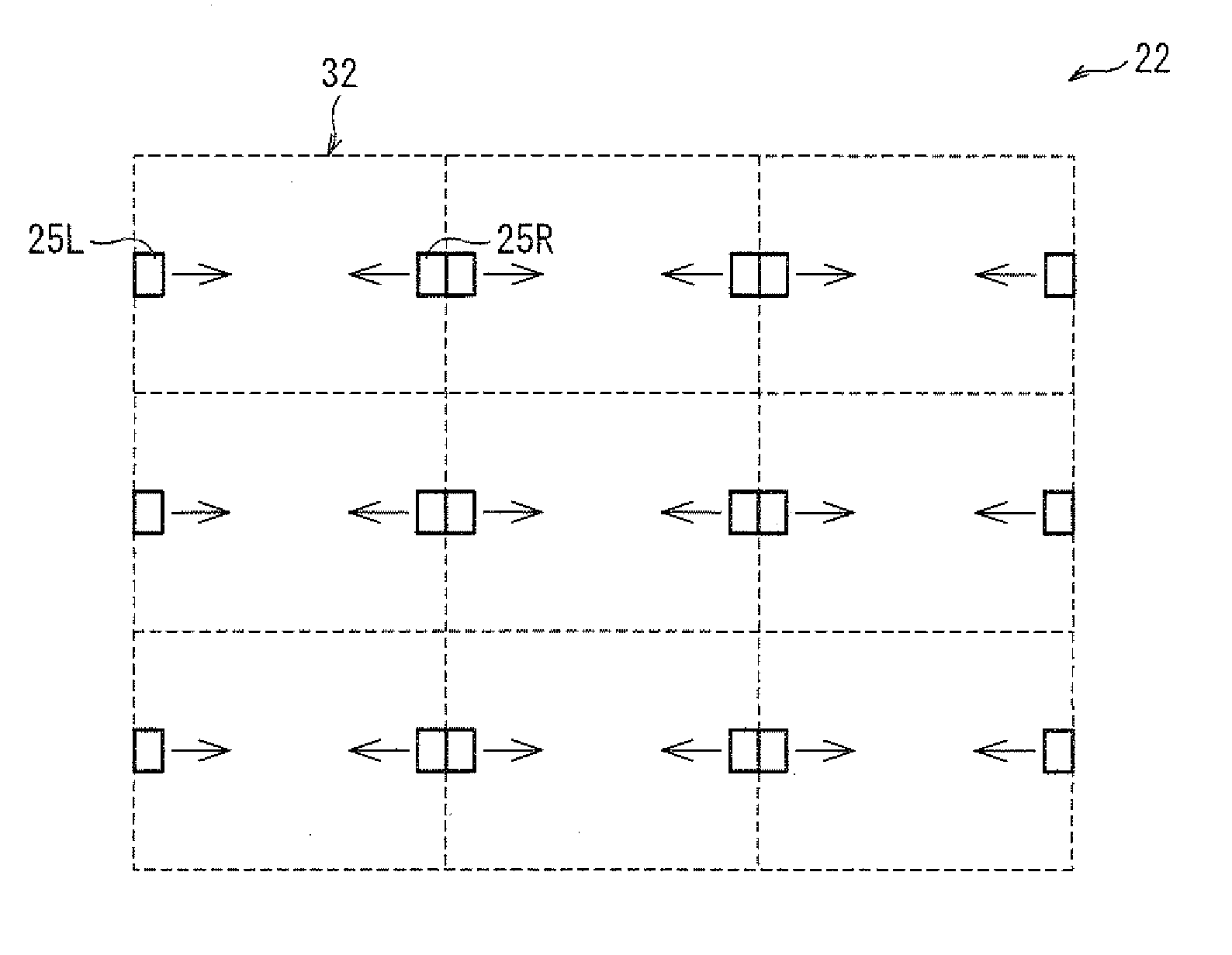
[0105]Embodiment 1 above describes a tandem-type backlight. In contrast, the present embodiment describes a tile-type backlight, which includes multiple light guides that are arranged in a plane and that do not overlap one another.

[0106]FIG. 5 is a cross-sectional view schematically illustrating a configuration of a liquid crystal display device 21 according to the present embodiment. FIG. 6 is an enlarged cross-sectional view of a part of the liquid crystal display device 21. The liquid crystal display device 21 includes: a backlight 22 (illumination device); and a liquid crystal display panel 23 so provided as to face the backlight 22. The liquid crystal display panel 23 has an arrangement similar to an arrangement of the liquid crystal display panel 3 of Embodiment 1.

[0107]The following describes a configuration of the backlight 22 included in the liquid crystal display devi...


PUM


Abstract

A backlight (illumination device; 2) of the present invention includes: multiple light sources (5); and multiple light guides (7, 17, . . . ) for causing surface emission of light from the light sources (5). Each of the light guides (7, 17, . . . ) includes: a light-emitting section (7b, 17b, . . . ) having a light-emitting surface (7a); and a light guide section (7c) for guiding, to the light-emitting section (7b, 17b, . . . ), light from the light sources (5), a light-emitting section (7b) of a first light guide (7) being provided above a light guide section (17c) of a second light guide (17) adjacent to the first light guide (7). A light amount adjusting section (11) for reducing the amount of light incident on it is provided between the light-emitting section (7b) of the first light guide (7) and the light-emitting section (17b) of the second light guide. This allows for production of an illumination device having further improved luminance uniformity.

Description

TECHNICAL FIELD[0001]The present invention relates to an illumination device used, for example, as a backlight of a liquid crystal display device, and also relates to a liquid crystal display device including the illumination device.BACKGROUND ART[0002]Liquid crystal display devices have become rapidly popular in place of cathode ray tube (CRT) based display devices in recent years. The liquid crystal display devices have been in widespread use in liquid crystal televisions, monitors, mobile phones, and the like, which take advantage of, e.g., energy saving, thin, and lightweight features of the liquid crystal display devices. One way to further take advantage of such features is to improve an illumination device (i.e., a so-called backlight) which is provided behind the liquid crystal display device.[0003]The illumination devices are roughly classified into a side light type (also referred to as an edge light type) and a direct type. The side light type is configured such that a li...

Claims


Application Information

Patent Timeline
IPC IPC(8): G09G3/36G02F1/13357
CPCG02B6/0028G02B6/0035G02B6/008G02B6/0078G02B6/0046
Inventor SUMINOE, SHINJIAJICHI, YUHSAKU
Owner SHARP KK
Why Eureka
Try Eureka