Eureka AIR delivers breakthrough ideas for toughest innovation challenges, trusted by R&D personnel around the world.

Image pickup apparatus

Inactive Publication Date: 2006-02-14
CANON KK
View PDF8 Cites 16 Cited by
  • Summary
  • Abstract
  • Description
  • Claims
  • Application Information

AI Technical Summary

Benefits of technology

[0034]The present invention has been made to solve the above-described problems. It is an object of the invention to provide an image pickup system, a lens unit and an image pickup apparatus capable of preventing a lowered light amount and crosstalk which may be caused by difference between the accumulation time of an image pickup element and the open / close timing of the shutter.

Problems solved by technology

The structure described above is, however, associated with the following problems.
If the former sufficient conditions are not satisfied, the exposure amount of an image may become insufficient, whereas if the latter necessary conditions are not satisfied, a crosswalk may occur between right and left images and the quality of a stereo image is degraded.
In such a case, there is a mismatch (shift) between the accumulation time and the fixed open / close timing of the liquid crystal shutters so that a light amount lowers or crosstalk occurs.
In FIG. 10, areas A indicated by solid oblique lines correspond to insufficient light amounts which result in a degraded image quality.
If the difference becomes larger, the accumulation time overlaps the accumulation time for the other liquid crystal shutter, which results in crosstalk.

Method used


Image

  • Image pickup apparatus
  • Image pickup apparatus
  • Image pickup apparatus

Examples


first embodiment

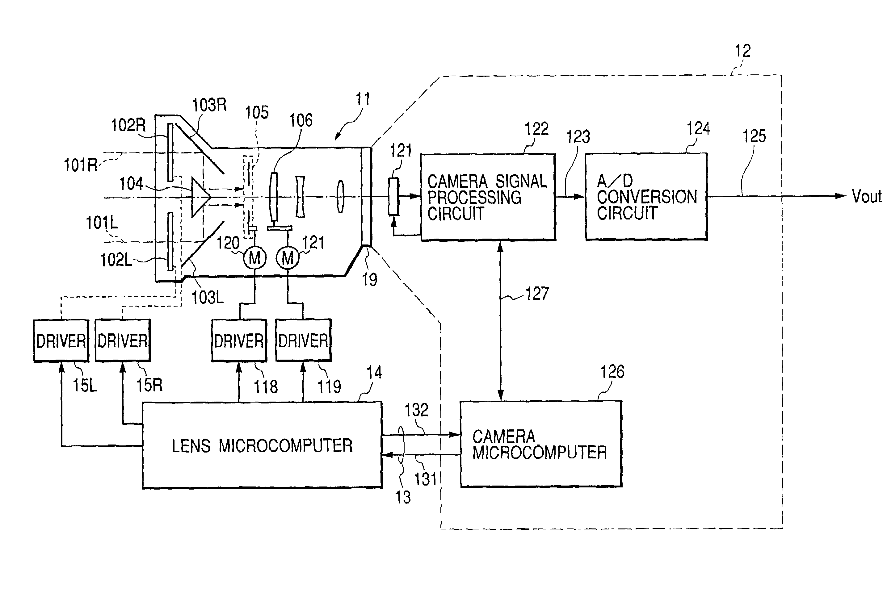
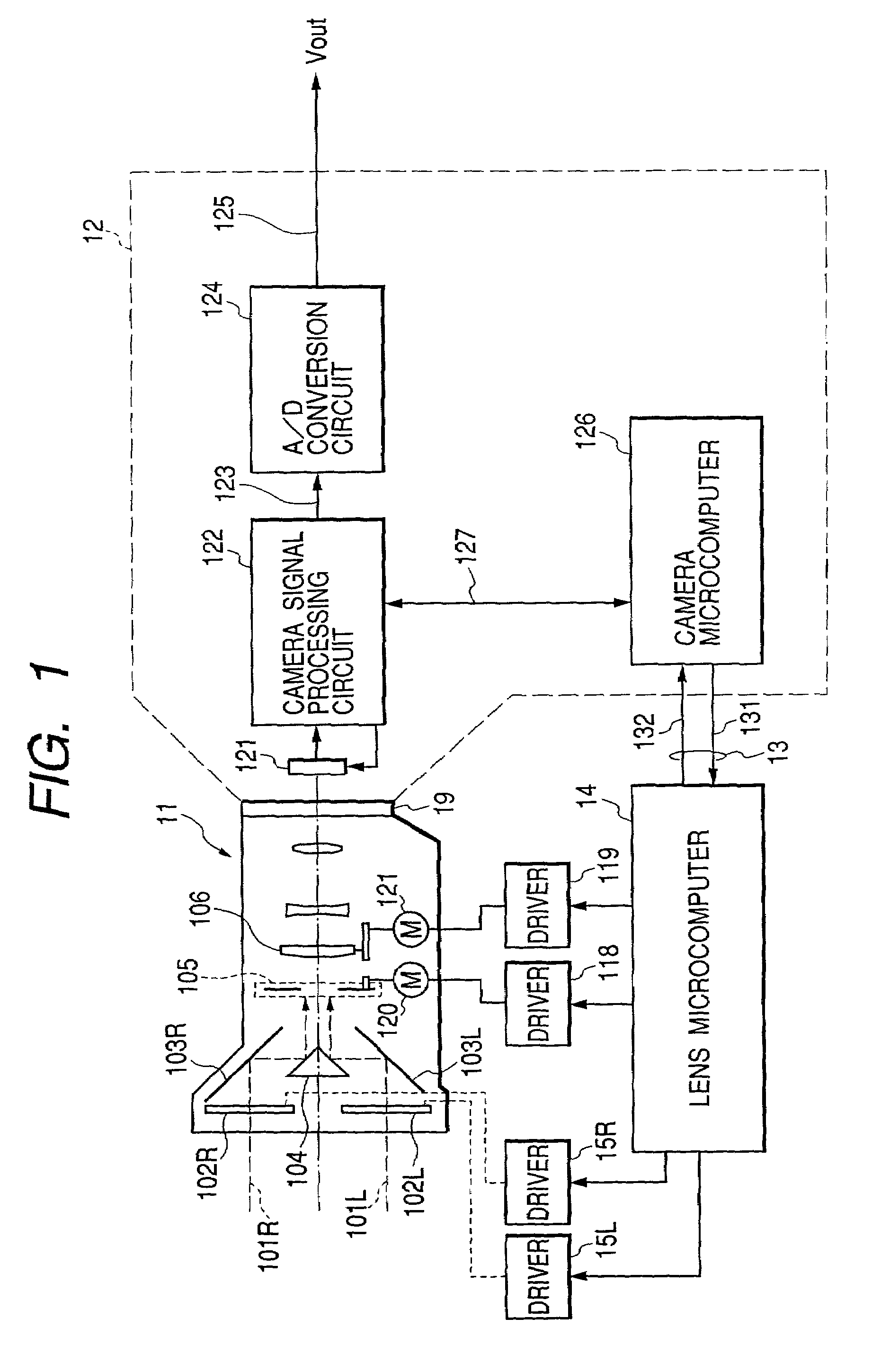
[0048]FIG. 1 is a diagram showing the structure of a stereo image pickup system according to a In FIG. 1, reference numeral 11 represents a lens unit for generating right and left parallaxes, this lens unit being separated into right and left optical systems on the side of the objective lens. A liquid crystal shutter (for right eye) 102R and a liquid crystal shutter (for left eye) 102L disposed in the right and left optical systems are operated so as to transmit a light flux (for right eye) 101R and a light flux (for left eye) 101L, respectively.

[0049]Transmitted light fluxes are converged into one light flux by a mirror (for right eye) 103R, a mirror (for left eye) 103L and a prism 104. The converged light flux passes through an iris 105 and through a lens exchange mount 19 via an optical system 106 constituted of lenses and the like, and is focussed on an image pickup plane of a CCD (image pickup element) 121 on the side of a camera unit 12. Only one of the right and left fluxes ...

third embodiment

[0078]FIG. 5 is a diagram showing the structure of a stereo image pickup system according to the present invention. In FIG. 5, reference numeral 201 represents right and left shutters (shutter 201R for right eye and shutter 201L for left eye) for inputting a time-divisional stereo image by repeating the open / close operation between the right and left shutters at a proper cycle. Reference numeral 202 represents right and left mirrors (mirror 202R for right eye and mirror 202L for left eye) for adjusting the direction (convergence angle) of right and left optical axes. Reference numeral 203 represents a prism for separating into right and left optical axes.

[0079]Reference numeral 204 represents a lens for converging an image. Reference numeral 205 represents an image pickup element such as a CCD for picking up a stereo image. Reference numeral 206 represents a video processing circuit which processes a signal supplied from CCD 205 to generate an image signal Vout.

[0080]Reference numer...

fourth embodiment

[0091]FIG. 6 is a diagram showing the structure of a stereo image pickup system according to the present invention. In FIG. 6, reference numeral 301 represents right and left shutters (shutter 301R for right eye and shutter 301L for left eye) for inputting a time-divisional stereo image by repeating the open / close operation between the right and left shutters at a proper cycle. Reference numeral 302 represents right and left mirrors (mirror 302R for right eye and mirror 302L for left eye) for adjusting the direction of right and left optical axes. Reference numeral 303 represents a prism for separating into right and left optical axes.

[0092]Reference numeral 304 represents a lens for converging an image. Reference numeral 305 represents a CCD for picking up a stereo image from the lens 304. Reference numeral 306 represents a video processing circuit which processes a signal supplied from CCD 305 to generate an image signal (video signal) Vout.

[0093]Reference numeral 307 represents a...


PUM


Abstract

An image pickup apparatus comprising: right and left optical systems; shutters disposed in correspondence with each of the right and left optical systems, for time-divisionally switching between incident light; a micro computer for controlling an open / close timing of the shutters; and an image pickup element for picking up an image input via the right and left optical systems, wherein the microcomputer variably controls the open / close timing of the shutters in accordance with exposure timing information of the image pickup element.

Description

BACKGROUND OF THE INVENTION[0001]1. Field of the Invention[0002]The present invention relates to an image pickup apparatus of a field sequential record type for picking up a stereo image with right and left parallaxes.[0003]2. Related Background Art[0004]A stereo image pickup system will be described.[0005]The stereo image pickup system described herein is of a field time-division type in which odd and even fields of an interlace video method such as NTSC are allocated to an image seen from a right eye (left eye) and an image seen from a left eye (right eye).[0006]Images picked up and recorded by the field time-division method are reproduced on a CRT monitor or the like, and viewed by using a pair of liquid crystal shutter spectacles which open and close synchronously with image timings. In this manner, a stereo image of the picked-up image can be viewed.[0007]FIG. 9 is a diagram showing the structure of a video camera to which the invention is applied. Referring to FIG. 9, referenc...

Claims


Application Information

Patent Timeline
IPC IPC(8): H04N5/235H04N5/238H04N5/335H04N5/353H04N5/359H04N5/372H04N13/00H04N13/02
CPCH04N13/021H04N13/0296H04N2013/0077H04N13/211H04N13/296
Inventor FUJIWARA, AKIHIROHARADA, TOMOHIRO
Owner CANON KK
Why Eureka
Eureka Blog
Learn More