Eureka AIR delivers breakthrough ideas for toughest innovation challenges, trusted by R&D personnel around the world.

Light guides

Active Publication Date: 2010-11-25
ITI SCOTLAND
View PDF13 Cites 25 Cited by
  • Summary
  • Abstract
  • Description
  • Claims
  • Application Information

AI Technical Summary

Benefits of technology

[0009](ii) an ink in contact with one or more of said microstructures, wherein said ink reduces the amount of light escaping from the light guide plate at said microstructure.
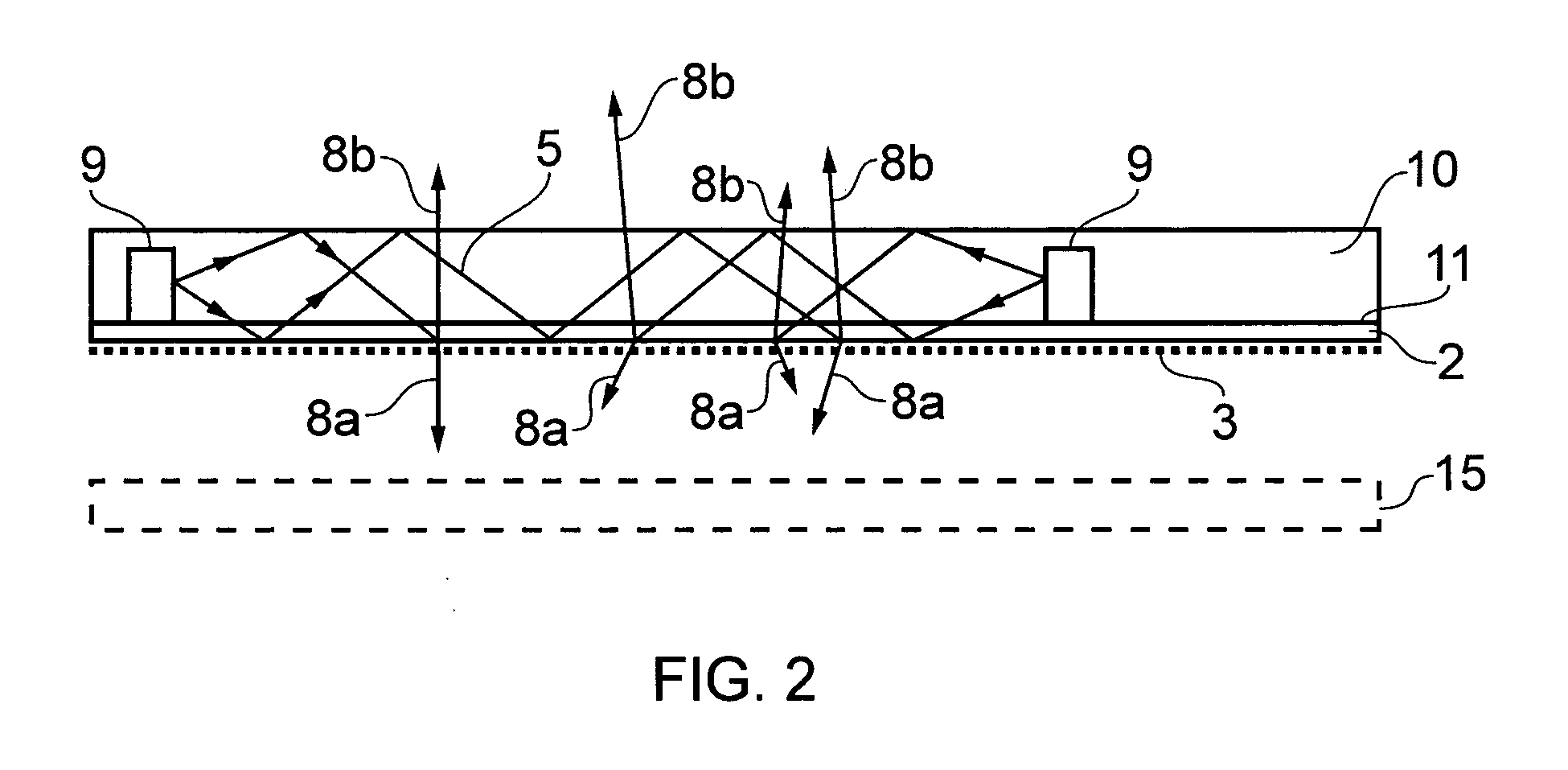
[0044]Such an arrangement provides a light guiding device that exhibits enhanced mechanical protection for the light sources. Furthermore, since there is no air gap between the output of the light sources and the light guide layer such an embodiment is simple to produce and exhibits enhanced optical coupling of the light within the device.

Problems solved by technology

However, there are a number of problems associated with such a technique, not least the expense associated with forming a suitable mould.
However, the optical quality associated with such polymer sheets is limited by the stamp quality and the associated manufacturing process.
Particularly as backlights become larger, these limitations become more critical.

Method used


Image

  • Light guides
  • Light guides
  • Light guides

Examples


example 1

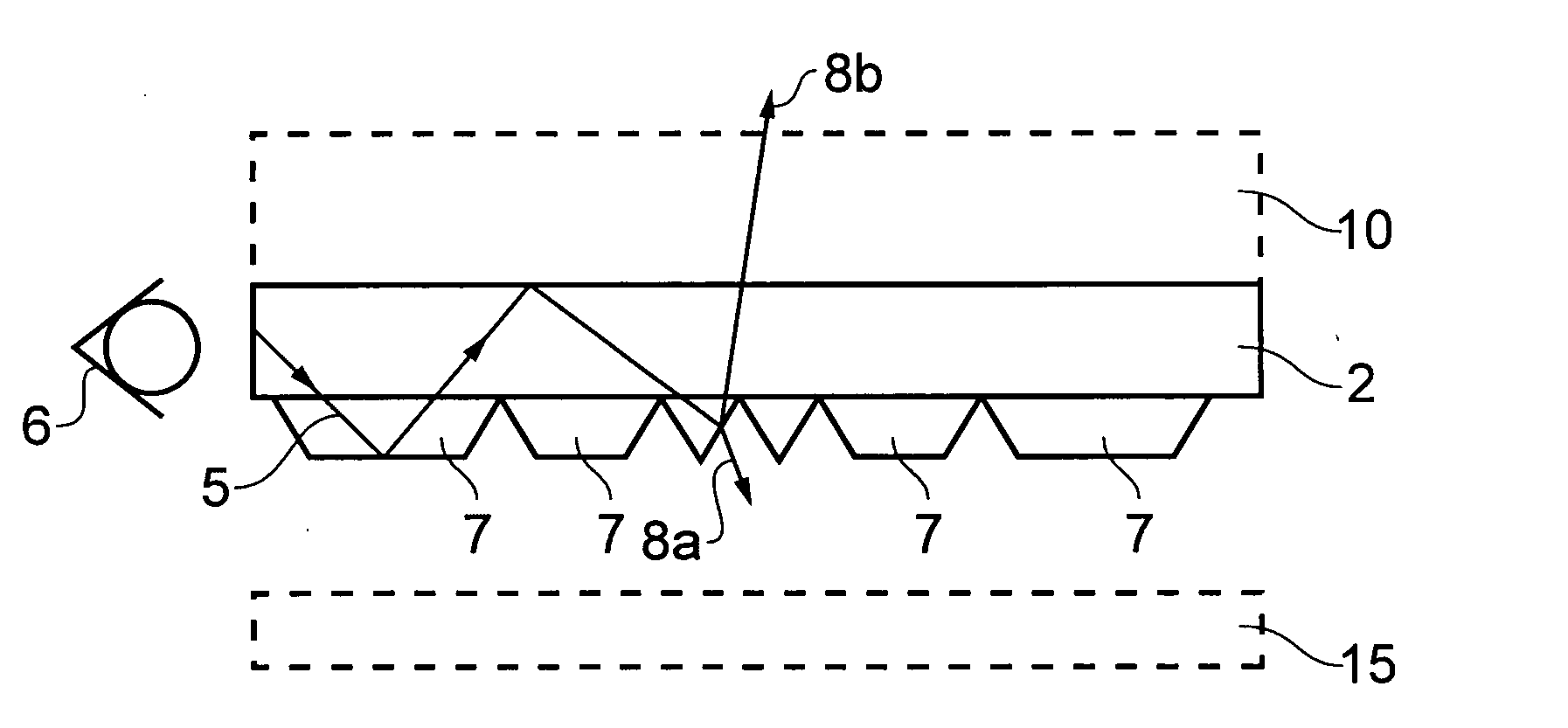
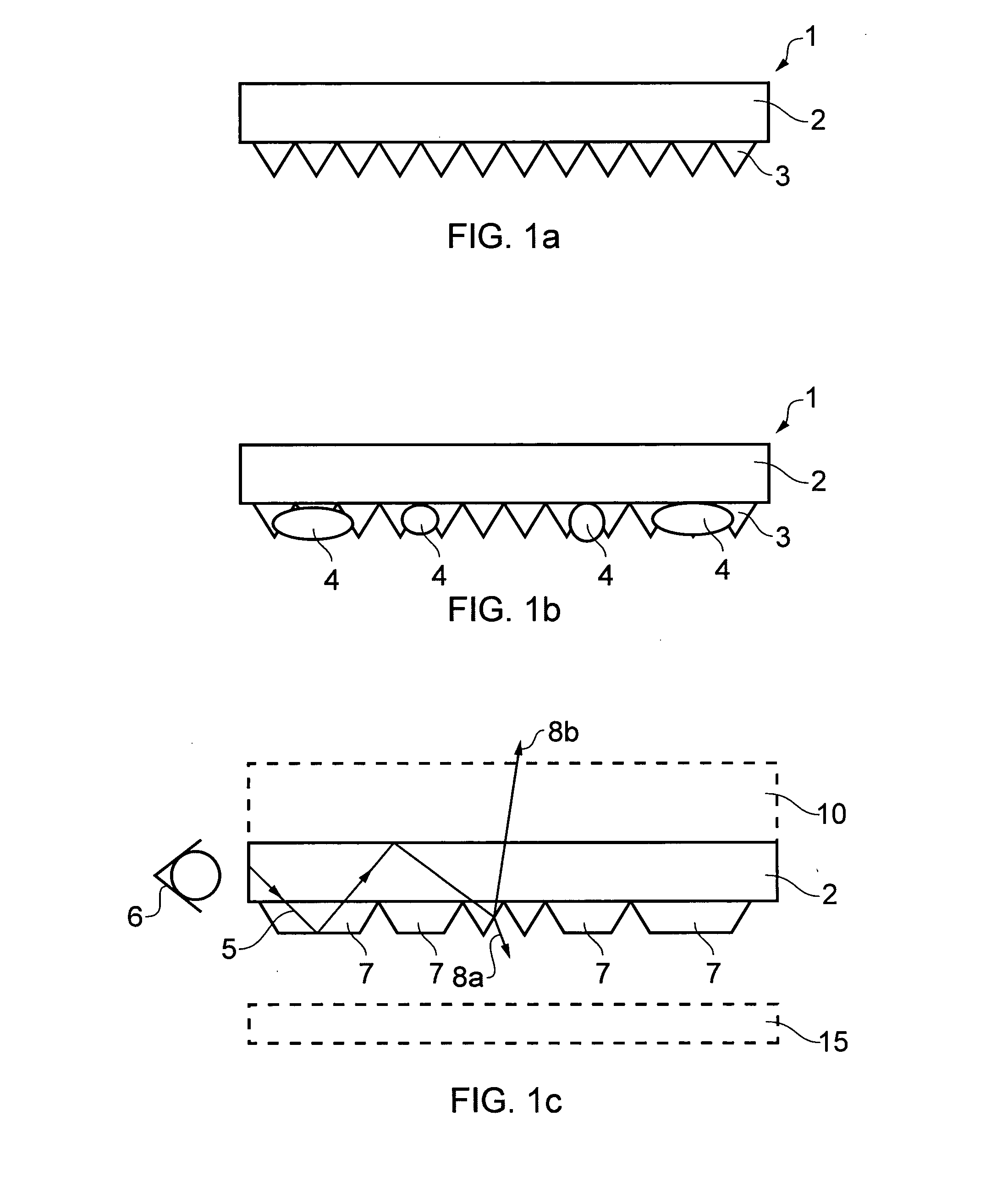
[0061]A light guide device was made as follows and with reference to FIG. 3 described above. 3M BEF III (Matte) was obtained from 3M and used as the film layer. Silver flake loaded solvent based polymer ink, which is a conducting ink, was screen printed onto the top side (non-microstructured side) of the BEF substrate. Windotex Gloss, an acrylic based, transparent UV curing polymer screen printable ink which is commercially available from MacDermid Autotype was printed on the reverse side of the substrate in a pattern to modify the BEF microstructure and provide the light scattering feature for uniform light output. In this example, the pattern was a series of small lines which were pitched across the surface at the 1000 micron scale and sized at the 500 to 1000 micron scale near the LEDs and sized at the 100 to 500 micron scale towards the middle of the microstructured film, and further away from the LEDs, resulting in minimal planarising of the microstructure. This arrangement res...

example 2

[0063]A number of experiments were undertaken to test the use of specular reflective ink in combination with the microstructured film used in Example 1. A pattern of mirrored prisms were deposited on the microstructures. By using a commercially available chrome, air drying ink, the acrylic microstructure / ink interface was made reflective from the acrylic side. The reflective ink was printed at 100 Dots Per Inch (DPI).


PUM


Abstract

This invention relates to film layer which is suitable for use in a light guide plate and methods of forming said film layer and light guide plate. The invention also relates to the light guide plate and light guide devices made therefrom. The film and light guide plate are suitable for use in a range of applications, particularly in connection with the backlighting of displays, for example, liquid crystal displays.

Description

FIELD OF THE INVENTION[0001]This invention relates to film layer which is suitable for use in a light guide plate and methods of forming said film layer and light guide plate. The invention also relates to the light guide plate and light guide devices made therefrom. The film and light guide plate are suitable for use in a range of applications, particularly in connection with the backlighting of displays, for example, liquid crystal displays.BACKGROUND OF THE INVENTION[0002]A number of routes and manufacturing processes exist for making light guide layers suitable for use in backlighting applications. Typically, a transparent polymer is injection moulded to form a thin plate with suitable surface features. The surface features disturb the total internal reflection of the light thus allowing light, guided inside the plate, to escape in a controlled manner.[0003]However, there are a number of problems associated with such a technique, not least the expense associated with forming a s...

Claims


Application Information

Patent Timeline
IPC IPC(8): G02F1/1335F21V7/22B41M1/12
CPCG02B6/0021G02B6/0065G02B6/0053
Inventor GOURLAY, JAMES
Owner ITI SCOTLAND
Why Eureka
Eureka Blog
Learn More