Shaft furnace and method for operating a furnace

a shaft furnace and furnace technology, applied in the field of shaft furnaces, can solve the problems of increasing production costs and the inability to increase the efficiency of modern shaft furnaces, and achieve the effects of less treatment gas, improved shaft furnace efficiency, and reduced production costs

Active Publication Date: 2010-10-07
THYSSENKRUPP AT PROTEC GMBH
View PDF5 Cites 3 Cited by
  • Summary
  • Abstract
  • Description
  • Claims
  • Application Information

AI Technical Summary

Benefits of technology

[0021]The invention furthermore relates to a shaft furnace, particularly blast furnace, cupola furnace, imperial smelter or waste incineration furnace which comprises a device for the charging of an upper region of the blast furnace with raw materials and at least a lower admission opening for admitting a treatment gas in a lower region of the shaft furnace, in order to smelt and/or at least partially reduce a part of the raw materials under the effect of the atmosphere prevailing within the shaft furnace. Furthermore, a control device is provided which is set in such a manner that the operating variables pressure p1 and/or volumetric flow {dot over (V)}1 of the treatment gas are subjected to a variation within the time span of ≦40 s, more preferably ≦20 s, preferred ≦5 s and particularly preferred ≦1 s. According to the invention, at least one addition opening spaced from the lower admission opening is provided for admitting addition gas, wherein an additional control device is provided which is set in such a manner that the operating variables pressure p2 and/or volumetric flow {dot over (V)}2, of the addition gas are varied at least at times and/or a shaft furnace gas line connected with the interior of the shaft furnace is provided for the discharge of gaseous reaction products, wherein a shaft furnace control device is provided, ...

Problems solved by technology

On the other hand the production costs are increased through the addition of oxygen so that the efficiency of a ...

Method used


Image

  • Shaft furnace and method for operating a furnace
  • Shaft furnace and method for operating a furnace

Examples


Embodiment Construction

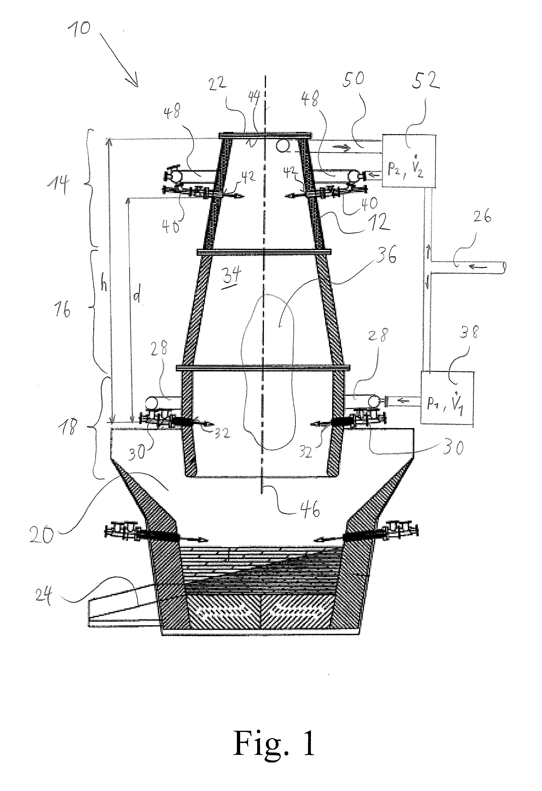
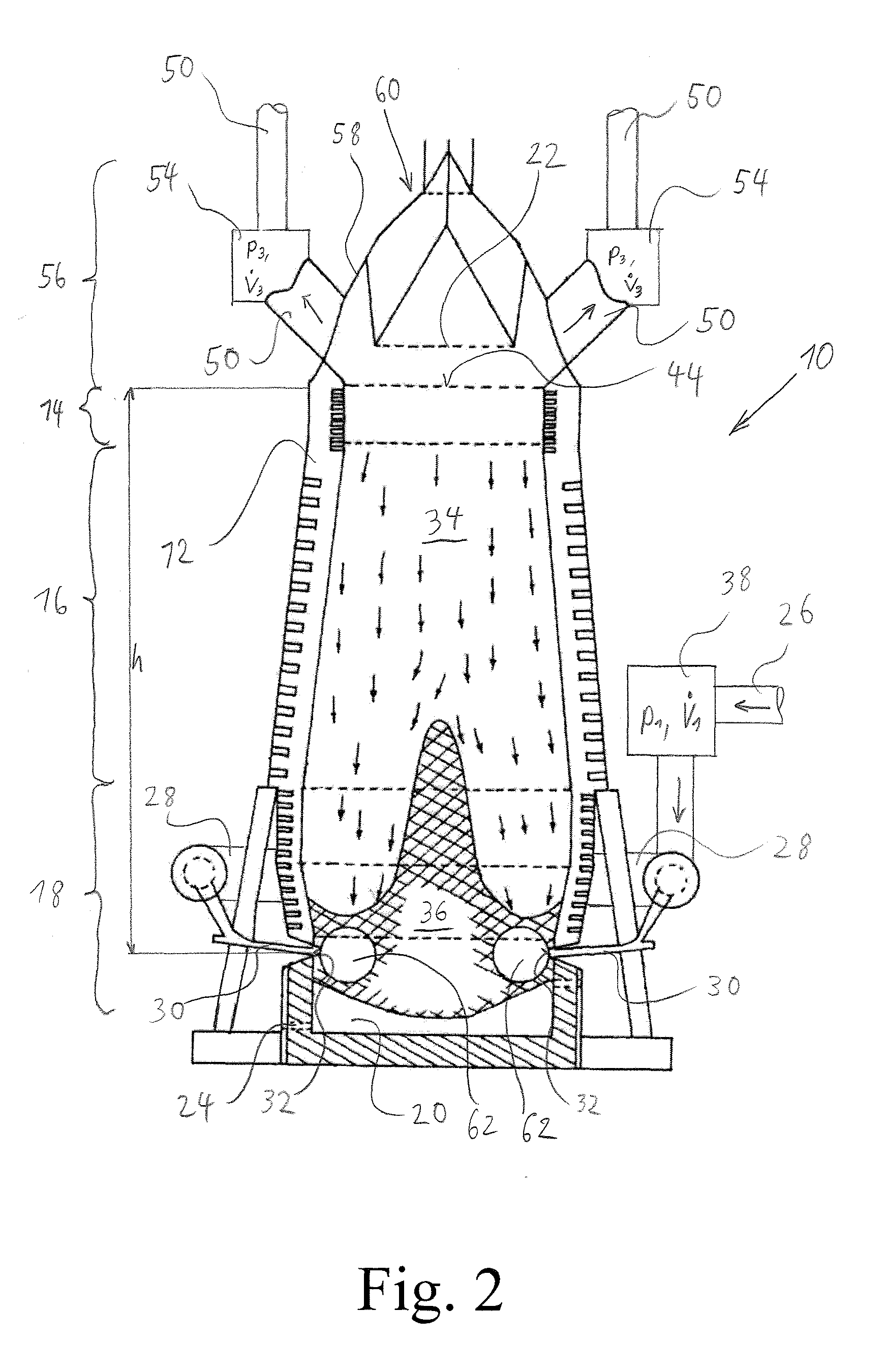
[0026]The shaft furnace 10 shown in FIG. 1 comprises a substantially tubular shaft furnace body 12 which can be roughly subdivided into an upper third 14, a middle third 16 and a lower third 18. The lower third 18 is followed by a sump 20 which accommodates and discharges via a drain 24 in the molten state the material added into the upper third 14 via a flap 22.

[0027]Via a feed line 26 treatment gas is directed to lower nozzles 30 via a lower ring line 28 connected in-between, which nozzles 30 introduce the dynamically modulated treatment gas into the interior 34 of the shaft reactor 10 via a lower admission opening 32. Near the admission openings 32 a reaction zone described as “raceway” or fluidised zone is formed which encloses a zone of low reactivity in the lower region described as “dead man”36. Between the feed line 26 and the admission opening 32 a control device 38 is connected, which is set in such a manner that the operating variables pressure p1 and / or volumetric flow {...


PUM

PropertyMeasurementUnit
Fractionaaaaaaaaaa
Fractionaaaaaaaaaa
Fractionaaaaaaaaaa

Abstract

The invention relates to a method for operating a shaft furnace (10). According to said method, an upper region (14) of the shaft furnace (10) is charged with raw materials which sink in the shaft furnace (10) under the influence of gravity. Part of the raw materials is melted and/or at least partially reduced by the action of the atmosphere inside the shaft furnace (10). A treatment gas is introduced in a lower region (18) of the shaft furnace (10) by means of at least one lower admission opening (32), said treatment gas at least partially influencing the atmosphere inside the shaft furnace (10). The introduction of the lower treatment gas is dynamically modulated such that, during the modulation, the operating variables, that is pressure p1 and/or volume flow (I), are varied at least temporarily over a time span of ≦40 s, especially ≦20 s, preferably ≦5 s and especially preferably ≦1 s. According to the invention, an addition gas is introduced via at least one addition opening (42) at a distance from the lower admission opening (32), the operating variables of the gas, that is pressure p2 and/or volume flow (II), being at least temporarily varied, and/or a shaft furnace gas is derived by means of a shaft furnace gas line (50) connected to the inside (34) of the shaft furnace (10), for removing gaseous reaction products, the operating variables of the shaft furnace gas, that is pressure p3 and/or volume flow (III), being at least temporarily varied. The variation of the operating variables of the addition gas and/or the shaft furnace gas is carried out according to the invention in such a way that the pressure p1 and/or the volume flow (I) inside (34) the shaft furnace (10) is at least partially increased.

Description

REFERENCE TO RELATED APPLICATIONS[0001]This application claims priority to German Application 10 2007 029 629.2 filed Jun. 26, 2007.FIELD OF INVENTION[0002]The invention relates to a shaft furnace as well as a method for operating a shaft furnace which for example can be employed as blast furnace, cupola furnace, imperial smelter or waste incineration furnace.BACKGROUND[0003]For the production of primary melt of iron, a shaft furnace configured as blast furnace is predominantly employed as main unit, while other methods merely have a corresponding share of only approximately 5%. This shaft furnace can operate according to the counterflow principle. Raw materials such as burden and coke are charged in the upper region of the shaft furnace of the furnace top and sink to the bottom in the shaft furnace. In a lower region of the furnace (blow mould level) a treatment gas (so-called blast air with a volume of 800-1 100 m3 / tRE depending on the size of the furnace) is blown into the furnac...

Claims


Application Information

Patent Timeline
IPC IPC(8): C22B1/00F27B1/10F27B1/26
CPCC21B5/06C21B7/002F27D17/004F27B1/16F27B1/26C21B7/007G10L21/038H04B1/667C21B2100/64
Inventor KONIG, GERDKONIG, WOLFRAMBABICH, ALEXANDERSENK, DIETER GEORGGUDENAU, HEINRICH-WILHELMHELDT, HANS-HEINRICH
Owner THYSSENKRUPP AT PROTEC GMBH
Why Eureka
Try Eureka