Dual fuel heating source

a heating source and dual fuel technology, applied in the field of heating sources, can solve the problems of device and certain components thereof having various limitations and disadvantages

Active Publication Date: 2010-12-30
DENG DAVID
View PDF107 Cites 52 Cited by
  • Summary
  • Abstract
  • Description
  • Claims
  • Application Information

AI Technical Summary

Benefits of technology

[0013]In some embodiments of a method, the fuel selector can be connected to a dual fuel pressure regulator and moving said fuel selector can determine a gas path from said dual fuel pressure regulator through said fuel selector. The dual fuel pressure regulator can include a first outlet and a second outlet, and moving said fuel selector to a first position can permit communication of gas from said first outlet to said controller and moving said selector to a second position can permit communication of gas from said second outlet to said controller. Further, in some methods, moving said fuel selector to a first position can permit communication of gas from said first outlet through said controller to said LP burner line and LP ODS line and moving said selector to a second position can permit communication of gas from said second outlet through said controller to an NG burner line and ODS line.

Problems solved by technology

However, such devices and certain components thereof have various limitations and disadvantages.

Method used


Image

  • Dual fuel heating source
  • Dual fuel heating source
  • Dual fuel heating source

Examples


Embodiment Construction

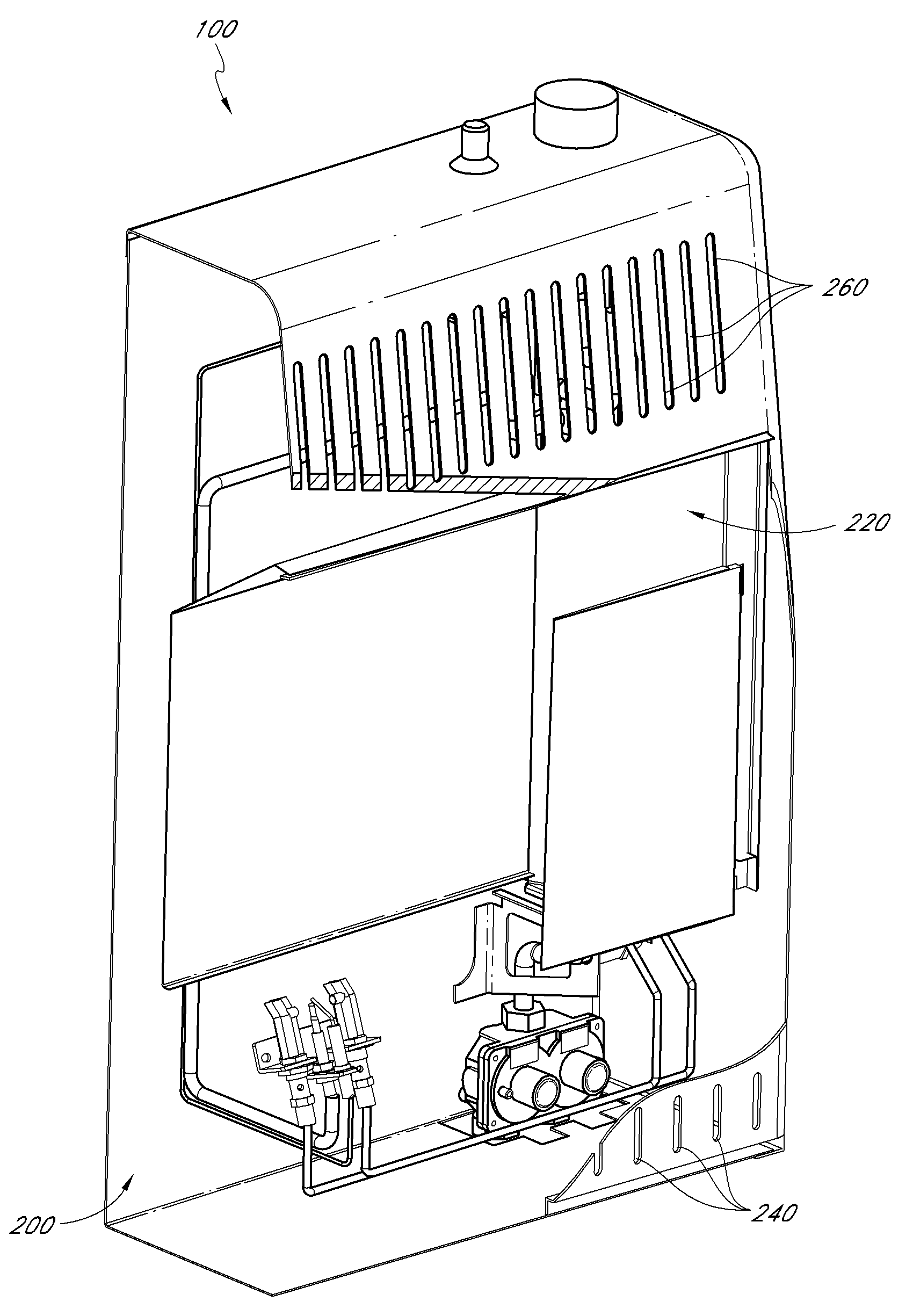
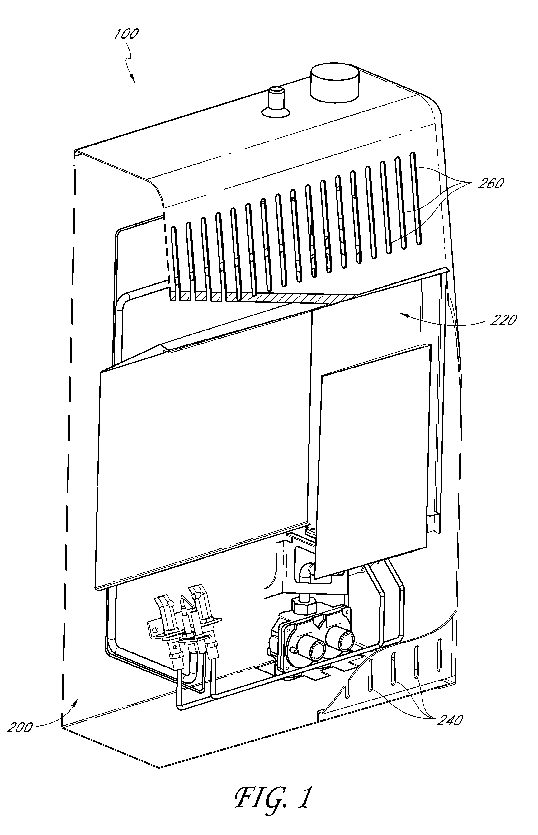
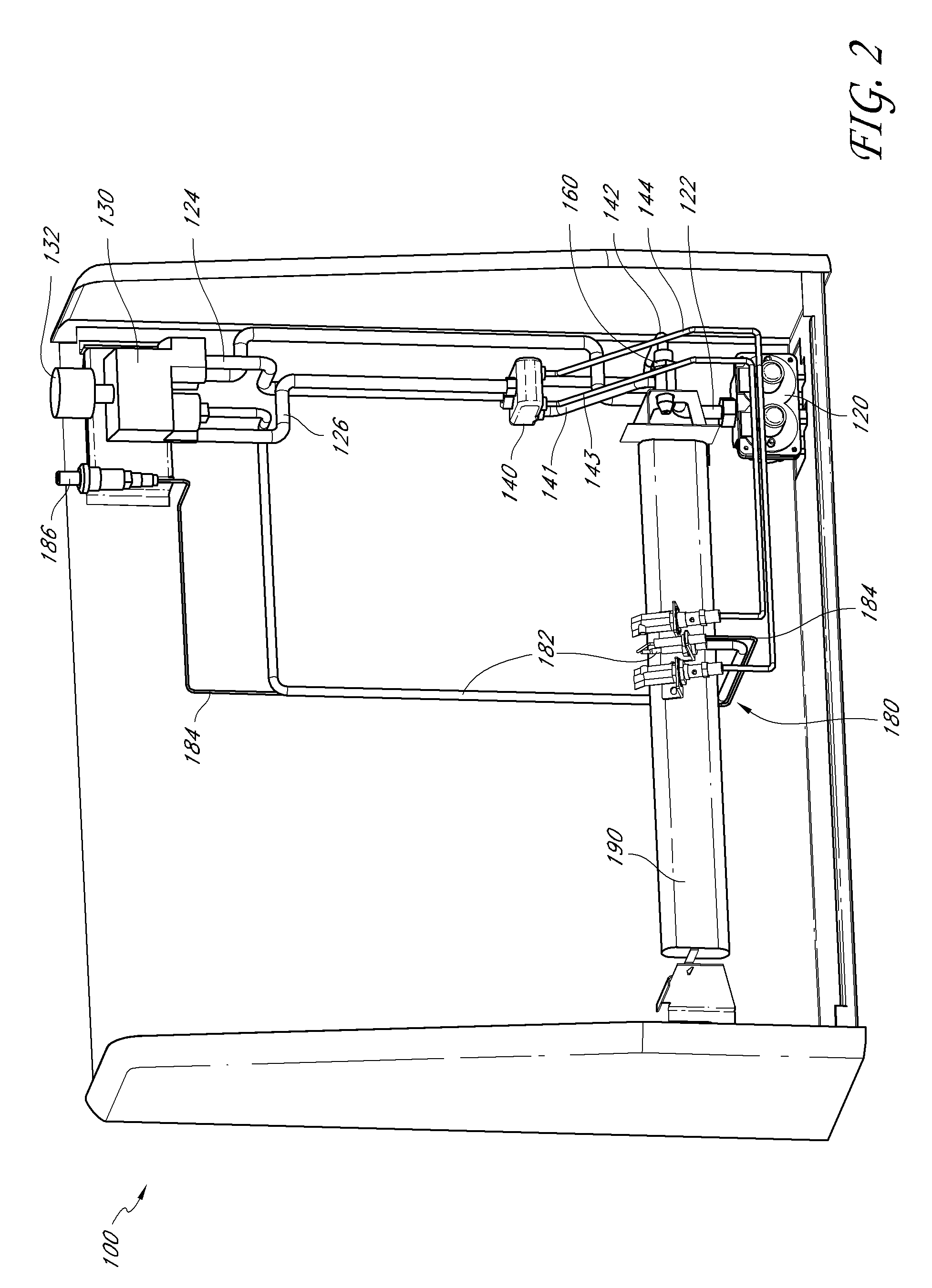
[0067]Many varieties of space heaters, fireplaces, stoves, ovens, boilers, fireplace inserts, gas logs, and other heat-producing devices employ combustible fuels, such as liquid propane and natural gas. These devices generally are designed to operate with a single fuel type at a specific pressure. For example, as one having skill in the art would appreciate, some gas heaters that are configured to be installed on a wall or a floor operate with natural gas at a pressure in a range from about 3 inches of water column to about 6 inches of water column, while others operate with liquid propane at a pressure in a range from about 8 inches of water column to about 12 inches of water column.

[0068]In many instances, the operability of such devices with only a single fuel source is disadvantageous for distributors, retailers, and / or consumers. For example, retail stores often try to predict the demand for natural gas units versus liquid propane units over a given season, and accordingly stoc...


PUM


Abstract

A dual fuel heating source can have a fuel selector valve for selecting between a first fuel and a second fuel different from the first. The dual fuel heating source may selectively have a regulator unit, and an outlet valve. The regulator unit can be configured to regulate the pressure of two different fuels. The outlet valve can be connected to the fuel selector valve such that selecting a fuel can determine the path fuel will flow through the outlet valve and also out of the heating source.

Description

CROSS-REFERENCE TO RELATED APPLICATIONS[0001]This application claims priority to U.S. Provisional Application Nos.: (1) 61 / 221,521, filed Jun. 29, 2009; (2) 61 / 221,520, filed Jun. 29, 2009; (3) 61 / 221,529, filed Jun. 29, 2009; (4) 61 / 221,528, filed Jun. 29, 2009; (5) 61 / 287,147, filed Dec. 16, 2009; (6) 61 / 286,355, filed Dec. 14, 2009; (7) 61 / 286,354, filed Dec. 14, 2009; (8) 61 / 286,352, filed Dec. 14, 2009; and (9) 61 / 304,373, filed Feb. 12, 2010; the entire contents of all of which are hereby incorporated by reference herein and made a part of this specification. The following U.S. patent application Nos. are also incorporated by reference herein and made a part of this specification: Ser. No. 11 / 443,484, filed May 30, 2006 (now U.S. Pat. No. 7,607,426); Ser. No. 11 / 443,446, filed May 30, 2006 (now U.S. Pat. No. 7,677,236); Ser. No. 11 / 443,492, filed May 30, 2006 (now U.S. Pat. No. 7,434,447); Ser. No. 11 / 443,473, filed May 30, 2006; Ser. No. 11 / 649,976, filed Jan. 5, 2007; Ser. N...

Claims


Application Information

Patent Timeline
Patent Type & Authority Applications(United States)
IPC IPC(8): F23C1/00
CPCF16K11/0836F23C1/08F23K5/005F23K5/06F24H3/006F23N2035/18F23N2037/02F23N2037/08F24C1/02F23N1/007Y10T137/86566Y10T137/86815Y10T137/87917Y10T137/86541Y10T137/86823Y10T137/87249Y10T137/86501Y10T137/87129Y10T137/87161Y10T137/86831F24H9/1881F23N2235/18F23N2237/08F23N2237/02
Inventor DENG, DAVID
Owner DENG DAVID
Why Eureka
Try Eureka