Capacitive acceleration sensor

a technology of acceleration sensor and capacitive force, which is applied in the direction of speed/acceleration/shock measurement, measurement devices, instruments, etc., can solve the problems of high pressure applied to the sensor, variation in the characteristics of the acceleration sensor, and breakage of the sealing structure, so as to prevent the degradation of the acceleration measurement accuracy of the sensor and prevent the sealing structure. , the effect of preventing the degradation of the sealing accuracy

Inactive Publication Date: 2011-01-20
MITSUBISHI ELECTRIC CORP
View PDF6 Cites 7 Cited by
  • Summary
  • Abstract
  • Description
  • Claims
  • Application Information

AI Technical Summary

Benefits of technology

[0009]The present invention has been made to solve the above problems. It is, therefore, an object of the present invention to provide a capacitive acceleration sensor constructed so as to prevent breaking of its sealing structure when the structure is sealed by transfer molding and also prevent degradation of the acceleration measuring accuracy of the sensor.

Problems solved by technology

Therefore, when a capacitive acceleration sensor is subjected to injection molding, a high pressure is applied to the sensor.
This high pressure has been found to break the sealing structure at the portion forming the air gap.
Such breaking of the sealing structure has resulted in breakage of the moving part and stationary part for detecting acceleration and also resulted in a foreign object entering into the air gap, causing a variation in the characteristics of the acceleration sensor.
It has been found, however, that such reduction in the injection molding pressure slows down the flow of molding resin and causes formation of voids in the molding resin, thus degrading the internal portion-protecting capability and hence reliability of the sealing structure.
Degradation of the reliability has also resulted from detachment of the capacitive acceleration sensor from the molding resin due to reduced adhesion between them.
It has been found, however, that if the support pillar is set in an electrically floating state, the moving part is displaced by the electrical action of the support pillar, thereby lowering the measuring accuracy of the acceleration sensor.

Method used


Image

  • Capacitive acceleration sensor
  • Capacitive acceleration sensor
  • Capacitive acceleration sensor

Examples


first embodiment

[0020]A first embodiment of the present invention will be described with reference to FIGS. 1 to 3. It should be noted that throughout the description of the first embodiment, like numerals represent like materials or like or corresponding components, and these materials and components may be described only once. This also applies to other embodiments of the invention subsequently described.

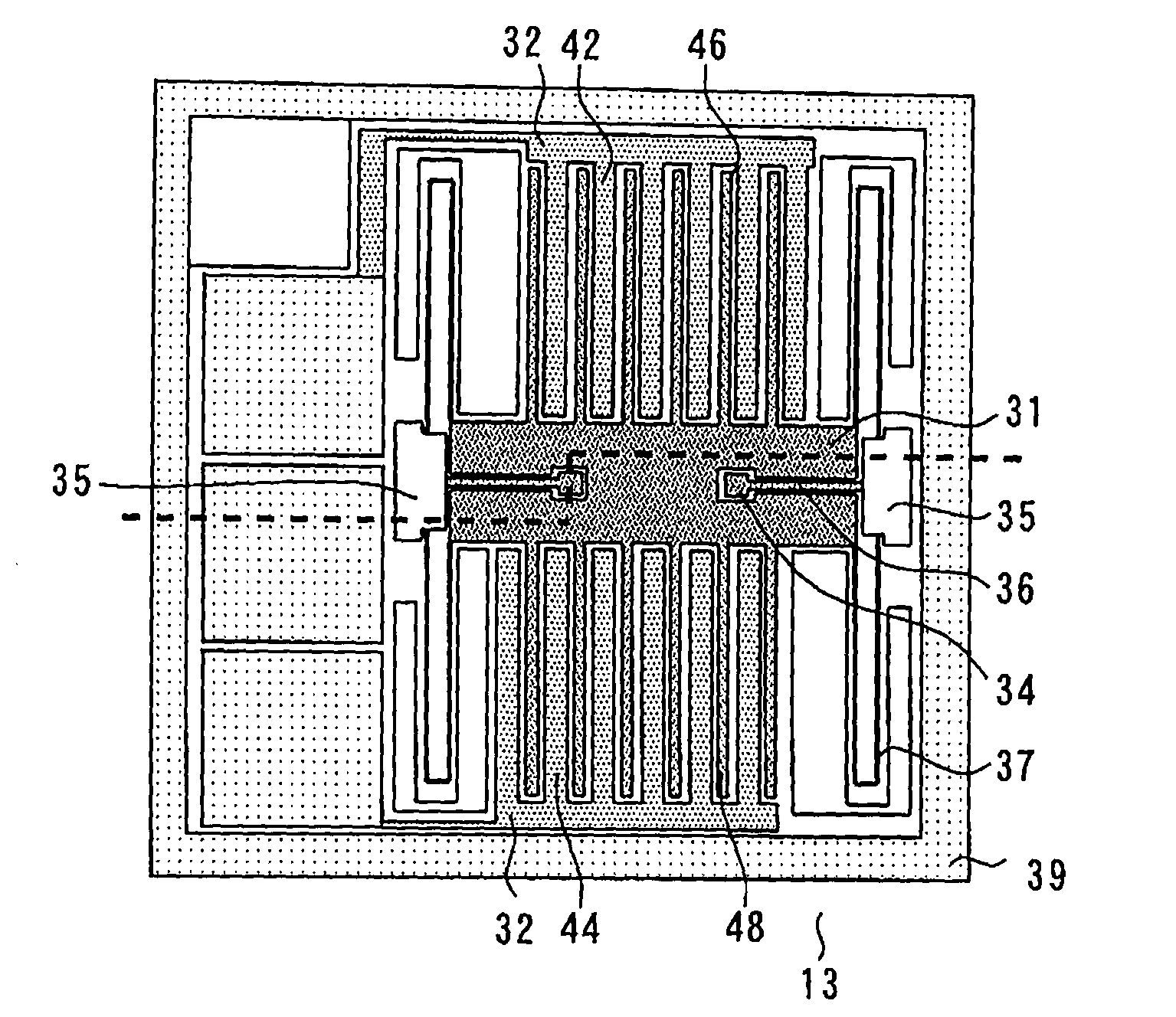
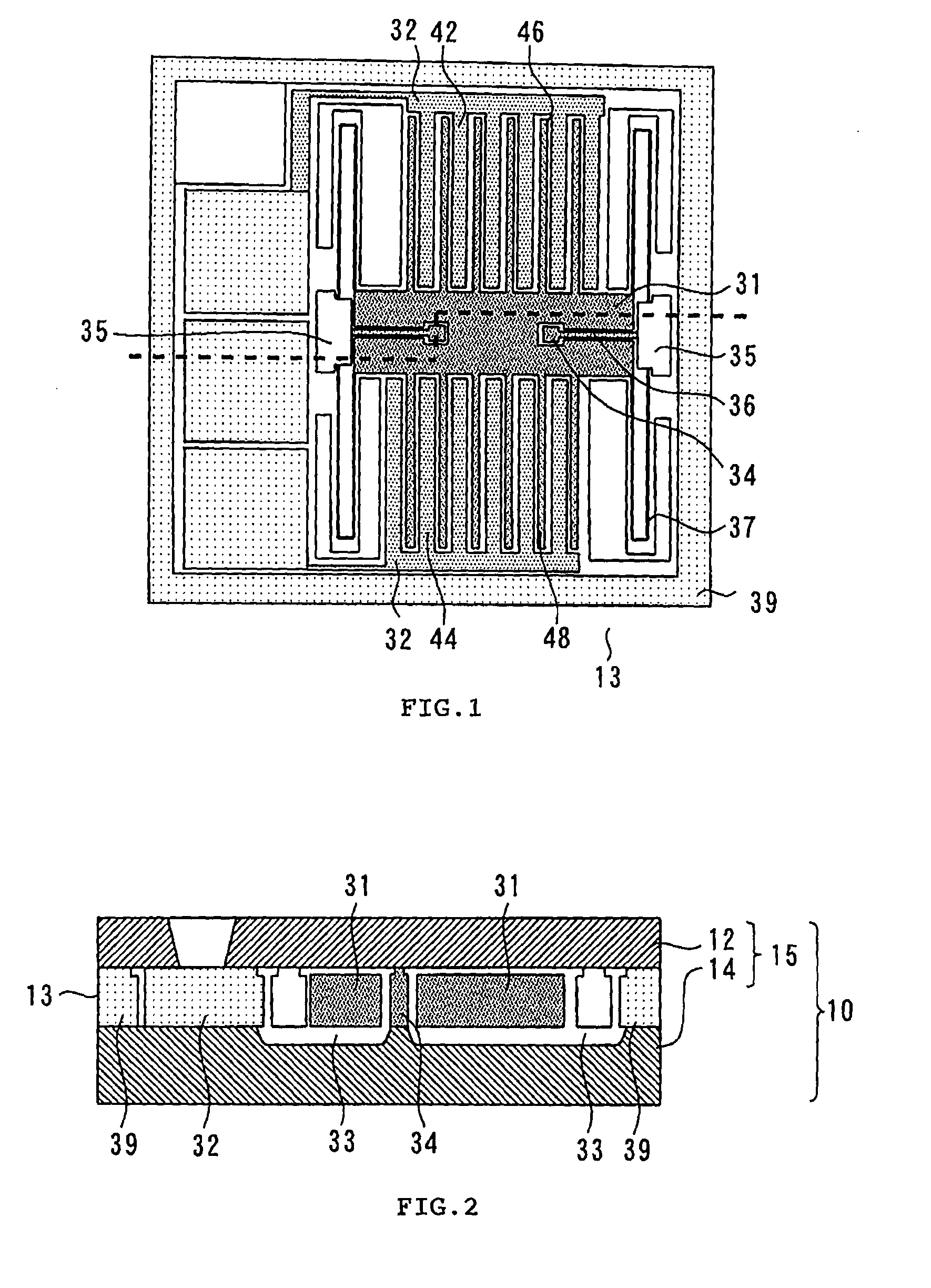
[0021]FIG. 1 is a plan view illustrating a semiconductor portion 13 of the present embodiment. This semiconductor portion 13 is adapted to detect acceleration. The semiconductor portion 13 includes an acceleration sensor moving part 31 (hereinafter referred to as the “moving part 31”) and an acceleration sensor stationary part 32 (hereinafter referred to as the “stationary part 32”). The moving part 31 includes moving comb teeth portions 46 and 48 formed to have a comb teeth shape, and the stationary part 32 includes stationary comb teeth portions 42 and 44 also formed to have a comb teeth shape....

second embodiment

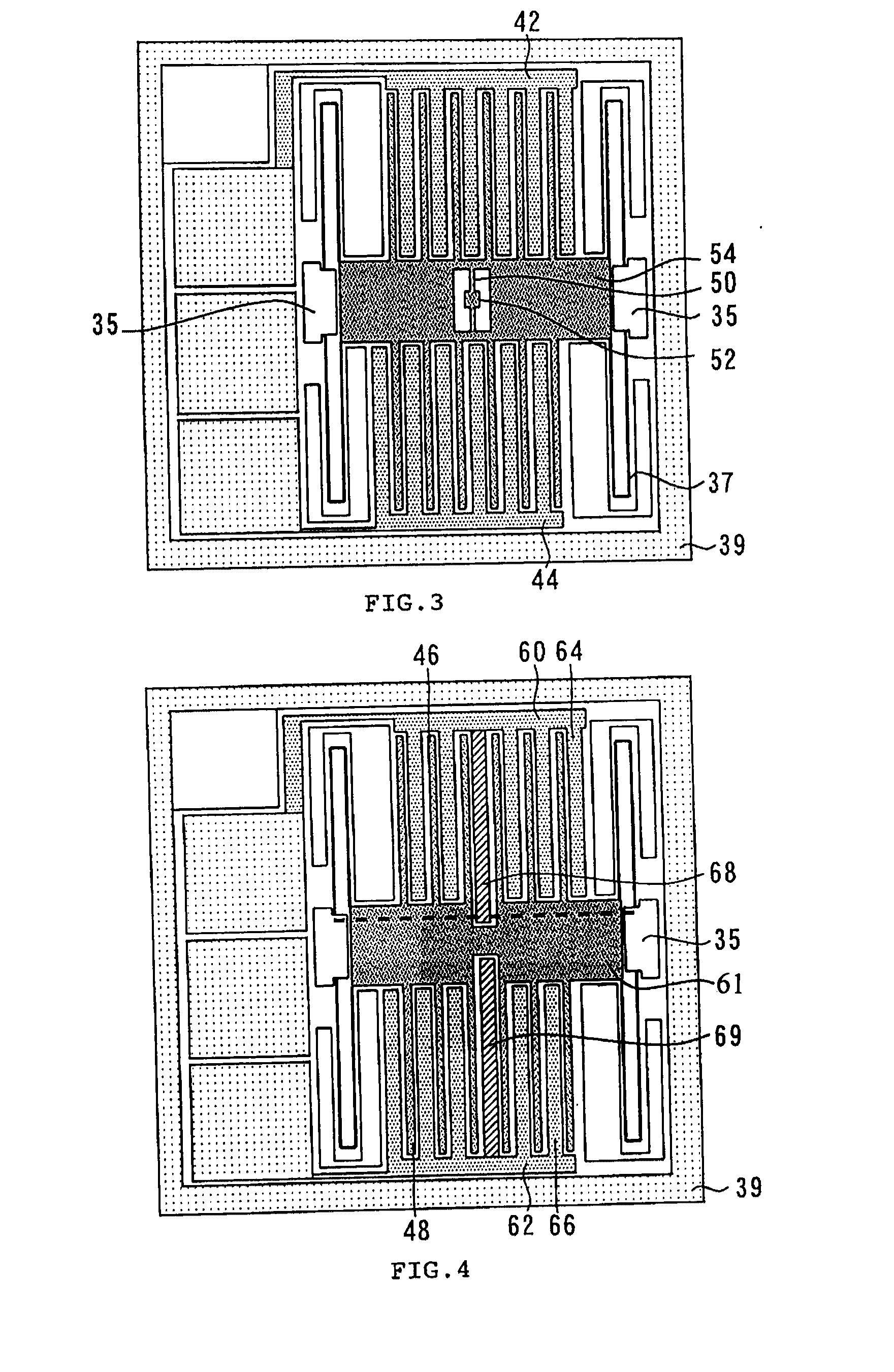
[0030]A second embodiment of the present invention will be described with reference to FIGS. 4 to 7. FIG. 4 is a plan view of a semiconductor portion of the second embodiment. A stationary comb teeth portion 64 and a moving comb teeth portion 46 together form a capacitor, and a stationary comb teeth portion 66 and a moving comb teeth portion 48 together form a capacitor. The stationary comb teeth portion 64 includes a comb tooth 68 having a support pillar. Likewise, the stationary comb teeth portion 66 includes a comb tooth 69 having a support pillar.

[0031]FIG. 5 is a perspective view of the stationary comb teeth portion 64. The comb tooth 68 of the stationary comb teeth portion 64 extends further than the other comb teeth and has a support pillar 70 at its tip, as shown in FIG. 5. The function of this support pillar 70 is the same as that of the support pillars 34 described in connection with the first embodiment. The comb tooth 69 with a support pillar shown in FIG. 4 has the same...


PUM


Abstract

A capacitive acceleration sensor includes an acceleration sensor moving part and an acceleration sensor stationary part together forming a capacitor for detecting acceleration, a sealing structure hermetically enclosing but not contacting the acceleration sensor moving part, and at least one support pillar enclosed by but not directly contacted by the acceleration sensor moving part, both ends of the at least one support pillar being in contact with inside walls of the sealing structure. The acceleration sensor moving part is electrically connected to the at least one support pillar.

Description

BACKGROUND OF THE INVENTION[0001]1. Field of the Invention[0002]The present invention relates to a capacitive acceleration sensor in which the moving part for detecting acceleration changes is disposed in a hermetically sealed air gap.[0003]2. Background Art[0004]Capacitive acceleration sensors measure acceleration by detecting a change in the capacitance of a capacitor. This capacitor includes a moving part (sometimes referred to as a “mass body”) and a stationary part. In the typical construction of a capacitive acceleration sensor, the moving part is supported by a beam so that the part is slightly displaced by acceleration and the resulting change in the capacitance of the capacitor is used to detect the acceleration.[0005]This moving part is hermetically enclosed in an air gap formed by a sealing structure so that the part is movable through a certain range of movement. Because of its being hermetically enclosed, the moving part is protected from foreign objects and moisture. T...

Claims


Application Information

Patent Timeline
Patent Type & Authority Applications(United States)
IPC IPC(8): G01P15/125
CPCG01P2015/0814G01P1/023
Inventor YAMAGUCHI, YASUOHORIKAWA, MAKIO
Owner MITSUBISHI ELECTRIC CORP
Why Eureka
Try Eureka