Tapered high pressure rotary feed valves

a high-pressure rotary and feed valve technology, which is applied in the direction of manufacturing tools, solventing equipment, other domestic objects, etc., can solve the problems of excessive leakage into the end-bell, long wear-in period of such valves, and waste of heat, so as to reduce the distortion of the shape as a result of unequal temperatures, the effect of reducing the pressure loss and shortening the tim

Active Publication Date: 2009-09-10
MST
View PDF8 Cites 4 Cited by
  • Summary
  • Abstract
  • Description
  • Claims
  • Application Information

AI Technical Summary

Benefits of technology

[0017]Initial operation of such a high pressure rotary valve when new or refurbished to factory specifications requires the body bore to be worn into a shape matching that of the rotor, so that the valve minimizes pressure loss when it has reached its equilibrium temperature distribution after operating for a long enough time.
[0018]It takes about eight hours for a tapered high pressure rotary feed valve of the size used in pulp processing to reach thermal equilibrium under continuous operation. Ideally, when starting such a valve one would give the valve at least three to four hours in which to stabilize. With a shorter time allowed for starting operation of the valve the thermal gradient between the top and bottom of the valve becomes larger, and the distortion of the shape as a result of unequal temperatures is greater.
[0019]The rotor stays round; it wants to seal all around on its circumference, on each end. At the same time the upper sector of the body bore, frustoconical when shaped at ambient temperature, takes on an oval section profile when the valve body reaches thermal equilibrium in operation. The non-uniform temperature profile thus prevented the rotor from sealing at the seal edges in the lower sector, because the rotor grows, radially, from heating-more than the surrounding body-and had to be pulled back axially to the last contact position, which is in the cooler upper sector of the body. Pulling the rotor back axially (thereby increasing the rotor-to-body clearance at the bottom) to compensate would make the leakage into the end-bell cavities worse.
[0020]The rotor contact first taking place at the top of the bore apparently led Bauer to surmise that the rotor had been deflected and at least to determine the rotor needed to be moved into the lower sector to mitigate the leakage (at the bottom) into the end-bell cavities, during the break-in or wear-in period.

Problems solved by technology

Since the rotor has to be moved axially into a position in contact with the housing, so that wear will occur where necessary, the power required to rotate the rotor during break-in is higher than is usual once a valve has been broken in, and leakage of pressurized gas or steam from the processing container occurs, wasting heat, during the break-in period.
The required wear-in period for such valves has been many hours long, often as much as two weeks.
Excessive leakage into the end-bells had resulted from the misfit of the rotor in the valve body with the rotor bearings centered.
It should be noted, the problem of leakage was particularly problematical when users started using sawdust for furnish in the early 1970's.
The downwardly eccentric adjustment of the rotor axis caused the lower sector of the bore to wear-in to a close fit first.
Quickly establishing a seal in the lower sector was paramount, because without it fines—especially sawdust—scaped past the seal at each end of the rotor in the bottom sector, causing end-bell plugging, excessive gas bypass into the inlet, and troublesome startups.
The real issue is one of thermal profiles in the materials of the housing and rotor to account for the shape and size of the housing and rotor in a condition of equilibrium once the valve has been in operation long enough to achieve its operating temperature during continuous operation.

Method used


Image

  • Tapered high pressure rotary feed valves
  • Tapered high pressure rotary feed valves
  • Tapered high pressure rotary feed valves

Examples


Embodiment Construction

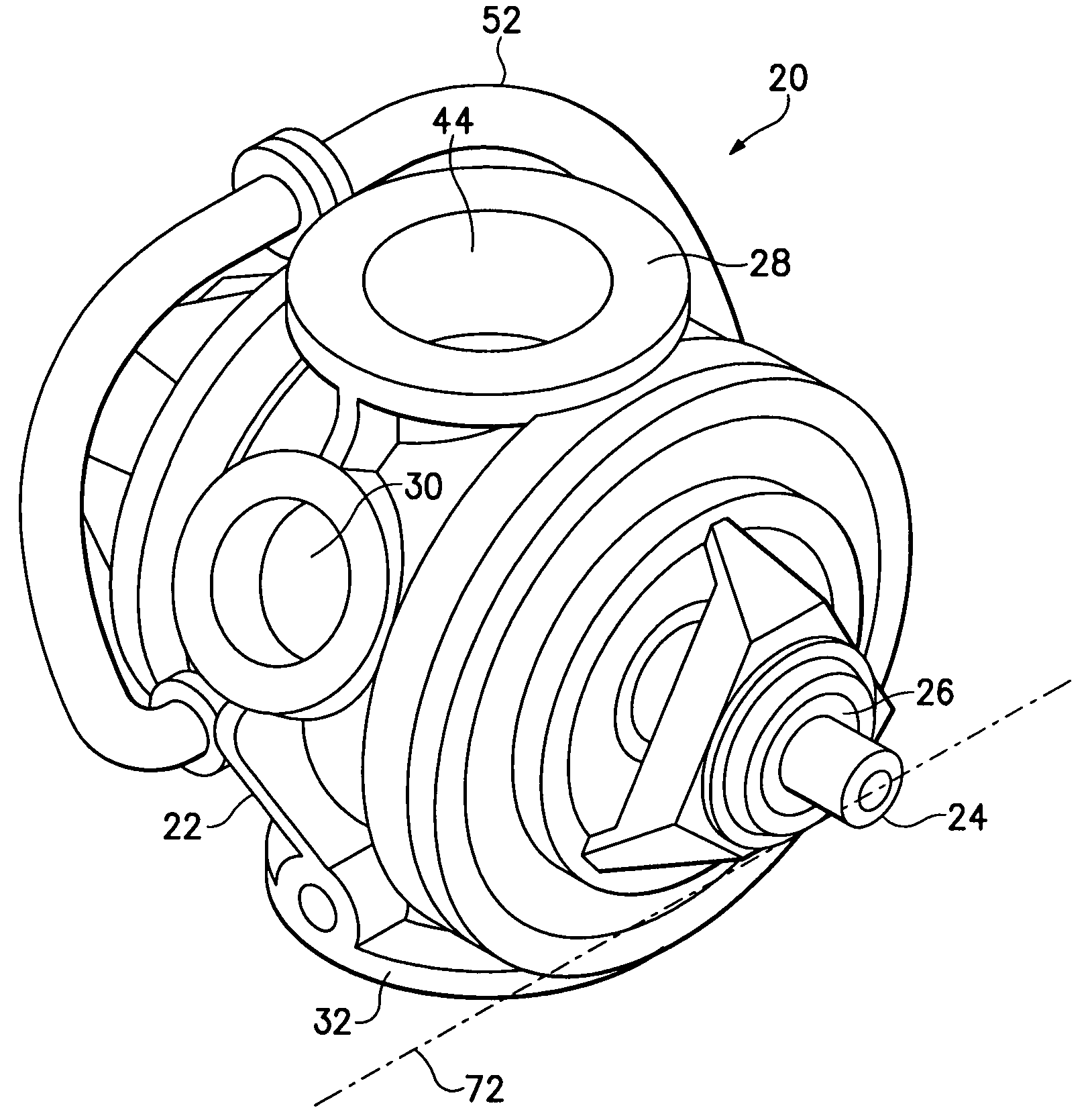
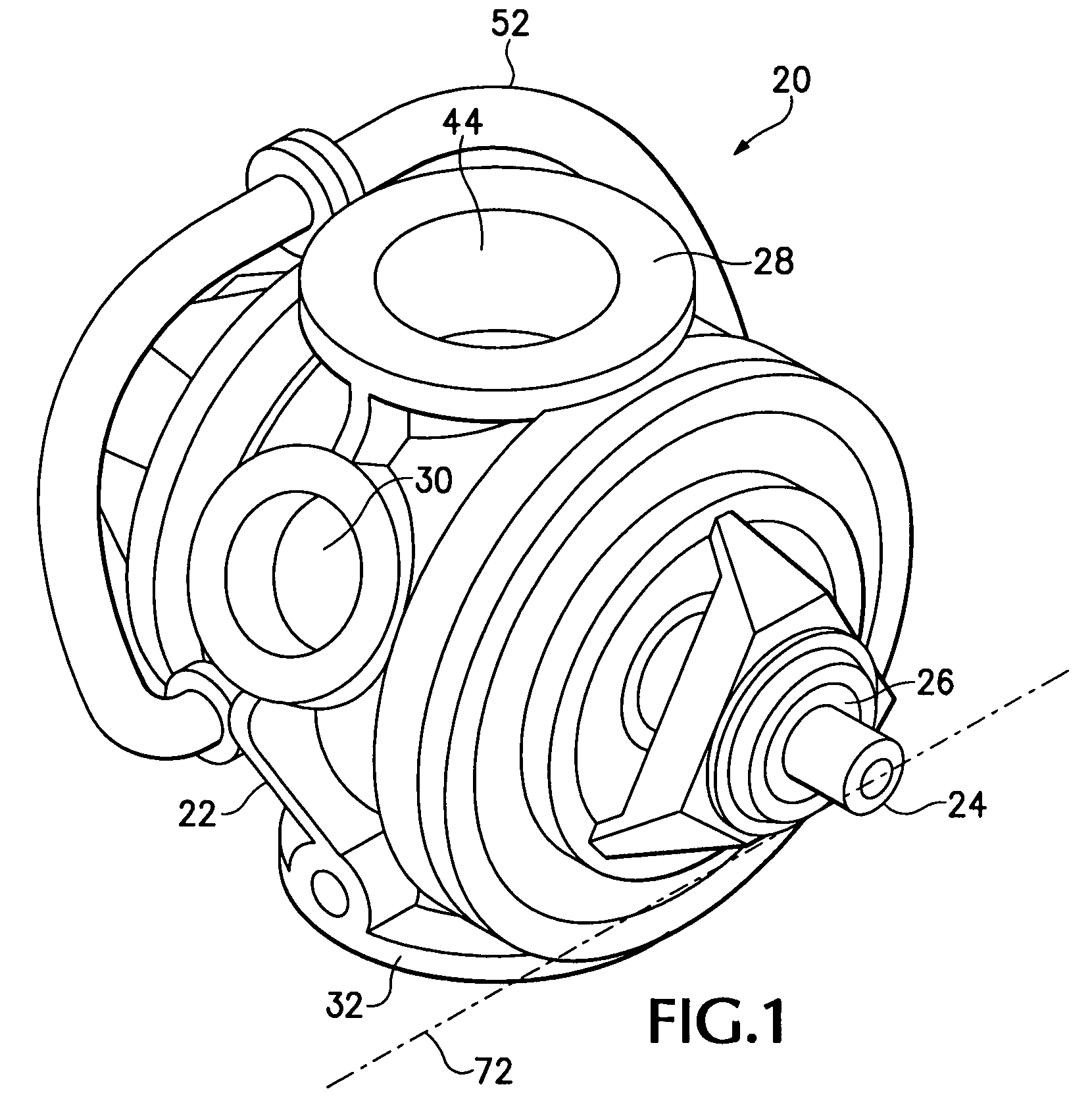
[0039]Referring to the drawings which form a part of the disclosure, FIG. 1 shows a tapered rotary feed valve 20 having a housing or body 22 and a rotor including a shaft 24 of which the ends are carried by radial bearings 26. The valve body 22 has an upper, or inlet side 28 that may include a flange or other fitting to receive a conduit carrying a flow of material such as wood chips to be fed through the feed valve 20. An exhaust port 30 may be provided to relieve pressure from within the body 22. A bottom or outlet side 32 may include a flange by which to mount the valve 20 on a top of a container of material kept at an elevated temperature and pressure, into which the valve 20 may be used to continuously feed additional particulate material.

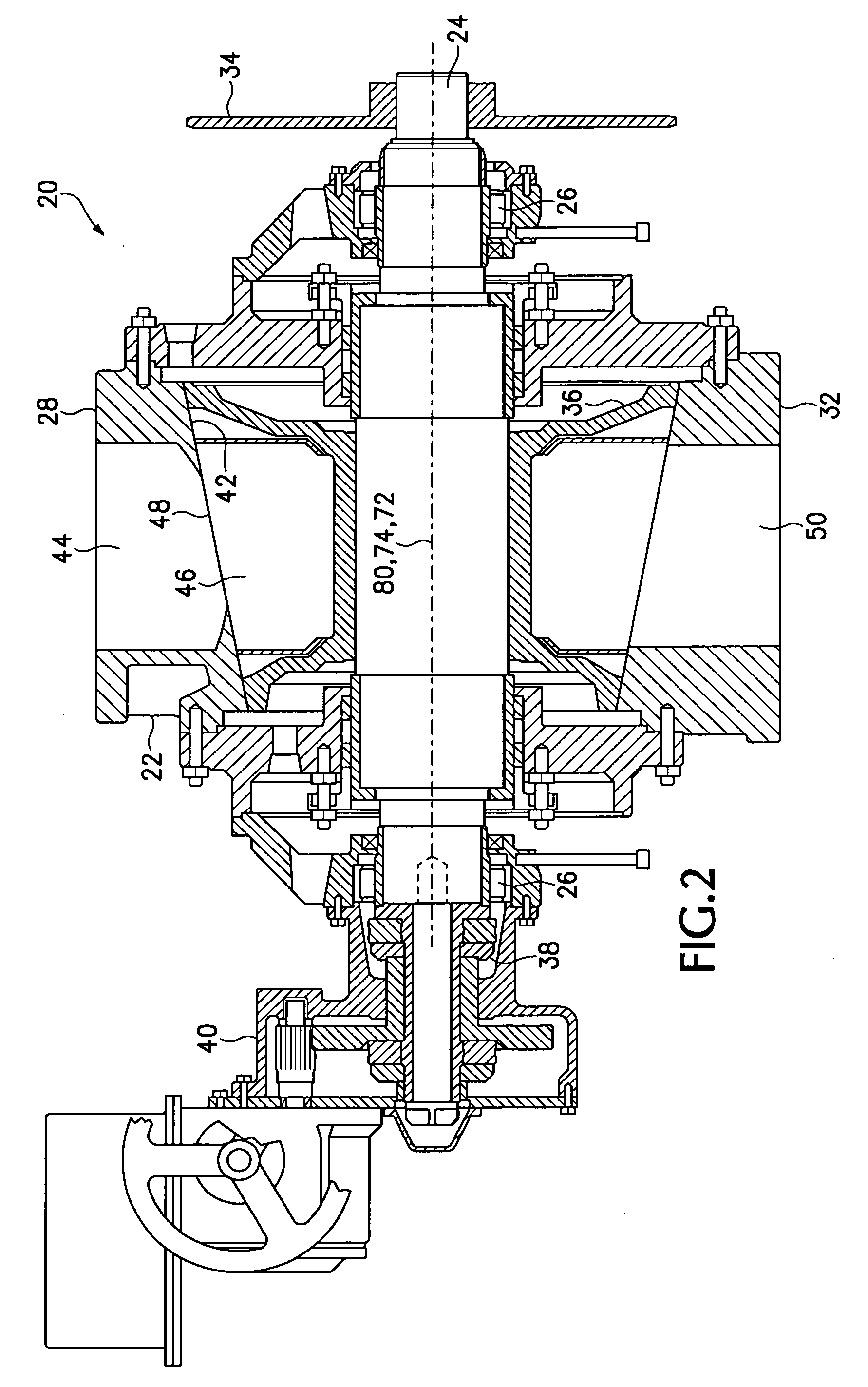
[0040]As shown in FIG. 2, the valve 20 may have a sprocket 34 mounted on the shaft 24 to rotate the tapered rotor 36 within the body 22. A thrust bearing 38 is adjustable by a mechanism 40 to move the rotor 36 axially relative to the body 22. ...


PUM

PropertyMeasurementUnit
lengthaaaaaaaaaa
diameteraaaaaaaaaa
pressureaaaaaaaaaa

Abstract

A tapered rotary feed valve is manufactured or refurbished for use in feeding materials into a high temperature environment, so as to reduce the time and expense of break-in operation, by shaping the tapered bore of the valve body at ambient temperature to have greater clearance around the rotor in a sector of the valve body that is cooler when the valve is at stable operating temperature. As a result, when the valve first reaches operating temperature after being manufactured or refurbished the rotor and the bore of the valve body nearly fit and can quickly wear in to fit each other closely.

Description

CROSS-REFERENCE TO RELATED APPLICATIONS[0001]This application claims the benefit of U.S. Patent Application Ser. No. 61 / 068,298 filed Mar. 5, 2008.TECHNICAL FIELD[0002]This disclosure relates to improvements in tapered high pressure rotary feed valves and, more particularly, to construction and overhaul of such valves so as to require a shorter time and less power to drive the valves for break-in after manufacture or overhaul.BACKGROUND AND SUMMARY[0003]Rotary material handling valves such as those disclosed, for example, in Starrett U.S. Pat. No. 3,273,758 and Starrett U.S. Pat. No. 3,750,902, are used for transferring particulate material into a pressurized environment at raised temperature. For example, such valves are used for feeding raw materials such as pulp wood chips and sawdust into a container of hot pulping liquor in the process of manufacturing paper. On a receiving side of such a valve, the chips are fed to the valve at temperatures near ambient atmospheric temperature...

Claims


Application Information

Patent Timeline
Patent Type & Authority Applications(United States)
IPC IPC(8): F16K5/00B21D51/16
CPCY10T29/49405F16K5/16D21C7/06
Inventor LACKEY, RAYMOND E.
Owner MST
Why Eureka
Try Eureka