Tire inflation system with discrete deflation circuit

a technology of deflation circuit and tire, which is applied in the direction of heavy duty tires, instruments, transportation and packaging, etc., can solve the problems of difficulty in manually checking and maintaining the target pressure for each and every tire, tire pressure might not be checked, and air may leakage from tires

Active Publication Date: 2015-03-10
HENDRICKSON USA L L C
View PDF26 Cites 21 Cited by
  • Summary
  • Abstract
  • Description
  • Claims
  • Application Information

AI Technical Summary

Benefits of technology

[0024]Yet another objective of the present invention is to provide a tire inflation system that does not employ electronic components, and thus is more economical, simpler, more dependable and more efficient than tire inflation systems of the prior art.
[0026]Yet another objective of the present invention is to provide a tire inflation system that optionally includes a feature which enables isolation of the tires from the air reservoir and other components of the system when the vehicle is parked in order to minimize pressure loss.
[0028]These objectives and others are obtained by the tire inflation system with discrete deflation circuit of the present invention. By way of additional example, the vehicle tire inflation system includes an air supply source in fluid communication with a plurality of tires of the vehicle. A pneumatic conduit extends between and is in fluid communication with the air supply source and the tires. A tire isolation pilot valve is in fluid communication with the pneumatic conduit and is equipped with means for monitoring a condition of the vehicle. The tire isolation pilot valve interrupts the fluid communication between the air supply source and the tires to pneumatically isolate the tires when the vehicle is in a parked condition, which minimizes a pneumatic pressure loss of the tires.

Problems solved by technology

However, it is well known that air may leak from a tire, usually in a gradual manner, but sometimes rapidly if there is a problem with the tire, such as a defect or a puncture caused by a road hazard.
The large number of tires on any given heavy-duty vehicle setup makes it difficult to manually check and maintain the target pressure for each and every tire.
This difficulty is compounded by the fact that trailers of tractor-trailers or trucks in a fleet may be located at a site for an extended period of time, during which the tire pressure might not be checked.
Any one of these trailers or trucks might be placed into service at a moment's notice, leading to the possibility of operation with under-inflated or over-inflated tires.
Such operation may increase the chance of less-than-optimum performance and / or reduced life of a tire in service as compared to operation with tires at the target pressure, or within an optimum range of the target pressure.
Moreover, should a tire encounter a condition as the vehicle travels over-the-road that causes the tire to become under-inflated, such as developing a leak from striking a road hazard, or over-inflated, such as increasing pressure from an increased ambient air temperature, the life and / or performance of the tire may be significantly reduced if the under-inflation or over-inflation continues unabated as the vehicle travels.
The potential for significantly reduced tire life typically increases in vehicles such as trucks or tractor-trailers that travel for long distances and / or extended periods of time.
Such a need to maintain the target pressure in each tire, and the inconvenience to the vehicle operator to manually check and maintain a proper tire pressure that is at or near the target pressure, led to the development of prior art tire inflation systems.
While being satisfactory for their intended functions, tire inflation systems of the prior art may experience disadvantages in certain situations.
More particularly, many prior art tire inflation systems are not capable of deflation.
As a result, when the air pressure in a tire increases to a level that is greatly above the target pressure due to increases in ambient air temperature, these systems are not able to reduce the pressure in the tires.
As a result, such prior art tire inflation systems may allow the tires to operate in a significantly over-inflated condition, which undesirably decreases performance of the tires and in turn decreases the life of the tires.
First, prior art tire inflation systems only maintain the inflation pressure in the tires at the target pressure, and lack the ability to accommodate an increased tire pressure based on operating conditions. More particularly, the desired target inflation pressure typically is selected by the vehicle operator based on what is known in the art as a cold inflation pressure or cold pressure, which is the inflation pressure of the tires when the vehicle remains parked. In many cases, the tire manufacturer recommends a target pressure that is at a cold pressure setting for a specific axle load.
However, as the vehicle operates and travels over-the-road, the energy and forces associated with the travel cause the temperature of each vehicle tire to increase.
Due to this lack of ability to accommodate an increased tire pressure based on operating conditions, prior art tire inflation systems often maintain the inflation pressure of the tires at a level that is below the optimum operating pressure, which decreases tire performance, and thus vehicle performance.
In the event that the vehicle operator attempts to prevent a prior art inflation system from deflating the tires down from the optimum operating pressure to the lower cold target pressure by selecting a target inflation pressure which is at the higher operating pressure, undesirable demands may be placed on the system.
More particularly, because the operating pressure is higher than the cold pressure, the operating pressure may approach or be at a pressure level that is not available in the vehicle air supply, or which would require the vehicle air supply to be maintained at an undesirably high level.
The requirement of maintaining such a pressure level in the vehicle air supply places undesirable demands on the tire inflation system, which in turn reduces the performance and / or the life of the system.
As a result, it is not practical to attempt to prevent prior art systems from deflating the tires down from the optimum operating pressure to the lower cold target pressure by selecting a target inflation pressure that is at the operating pressure.
A second disadvantage of prior art tire inflation systems is that most systems which are capable of both inflation and deflation are electronically controlled, which is undesirably expensive, complex, and potentially undependable.
For example, electronically-controlled systems typically involve electronically-operated solenoid valves, electronic controllers, and other electronic components, which are expensive and are often complex to install and configure.
In addition, these electrical components require the use of the electrical system of the vehicle, which may be unreliable or even non-functional at times, and in turn renders the operation of the tire inflation system unreliable and potentially non-functional.
A third disadvantage of prior art tire inflation systems is that the electronic systems are not constant-pressure systems.
More particularly, when the system is not performing inflation, the pneumatic conduit of the system is exhausted to atmosphere and thus does not actively monitor tire pressure.
Because such prior art systems are capable of only providing a periodic check of tire pressure, any inflation to bring the tires to the target pressure only takes place following the periodic check.
This lack of ability of prior art systems to continuously monitor tire pressure and dynamically respond to pressure changes undesirably reduces the ability of the system to actively or quickly respond to reduced tire pressure conditions, such as in the case of an air leak.
Moreover, as mentioned above, the electronic controls that are employed by prior art tire inflation systems to determine when it is necessary to trigger or commence inflation are expensive, complex, and require power from the electrical system of the vehicle, which may be unreliable.
A fourth disadvantage of prior art tire inflation systems occurs in certain pneumatically-controlled systems which are constant-pressure systems, that is, systems that maintain air pressure at all times in a pneumatic conduit extending between the vehicle air reservoir and the tires.
As is known to those skilled in the art, when a vehicle is parked for an extended period of time, the pneumatic pressure in the air reservoir may drop or bleed down due to small air leaks that are typical in any pneumatic system.
This re-inflation process typically takes a great deal of time and places repeated demands on the tire inflation system, which may reduce the life of the system.
In addition, the vehicle operator may not wait for the tires to be re-inflated to the target pressure before operating the vehicle, which in turn causes the tires to be operated in an under-inflated condition until the target pressure is reached.
Such operation reduces the life of the tires.
A fifth disadvantage of prior art tire inflation systems occurs in certain pneumatically-controlled, constant-pressure systems that do not include a wheel valve that is capable of deflation.
More particularly, without a wheel valve that is capable of deflation, such prior art systems cannot respond to excessive increased tire pressure from an increased ambient air temperature, as described above for prior art systems that are not capable of deflation.
As a result, such prior art tire inflation systems may allow the tires to operate in a significantly over-inflated condition, which undesirably decreases performance of the tires and in turn decreases the life of the tires.

Method used


Image

  • Tire inflation system with discrete deflation circuit
  • Tire inflation system with discrete deflation circuit
  • Tire inflation system with discrete deflation circuit

Examples


first embodiment

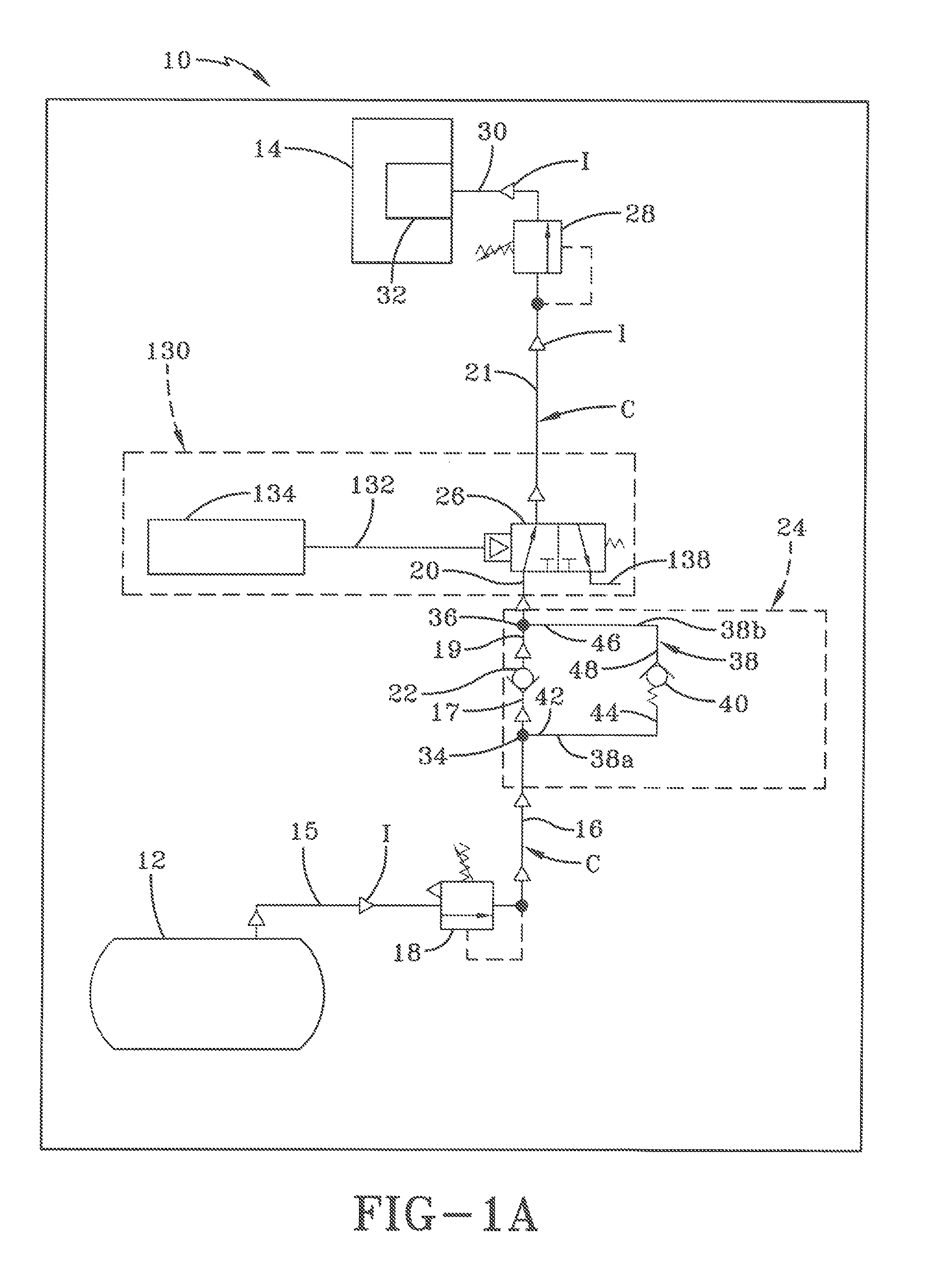
[0058]The desirable effect of the use of fixed differential X in deflation circuit 24 of first embodiment tire inflation system 10 is illustrated by the operation of the system. More particularly, as described above, the vehicle operator or a technician selects a target pressure by adjusting supply valve 18 using means that are placed in a convenient location inside the vehicle cab, or outside of the vehicle cab, such as on the trailer of a tractor-trailer, depending on system requirements. As shown in FIG. 1A, when inflation of tires 14 is required, supply valve 18 is opened or actuated, enabling air to flow from supply tank 12, through first pneumatic conduit section 15, through the supply valve and to second pneumatic conduit section 16, first tee fitting 34 of deflation circuit 24 and third pneumatic conduit section 17. First check valve 22 ensures that air continues to flow from third pneumatic conduit section 17 through fourth pneumatic conduit section 19 to second tee fitting...

second embodiment

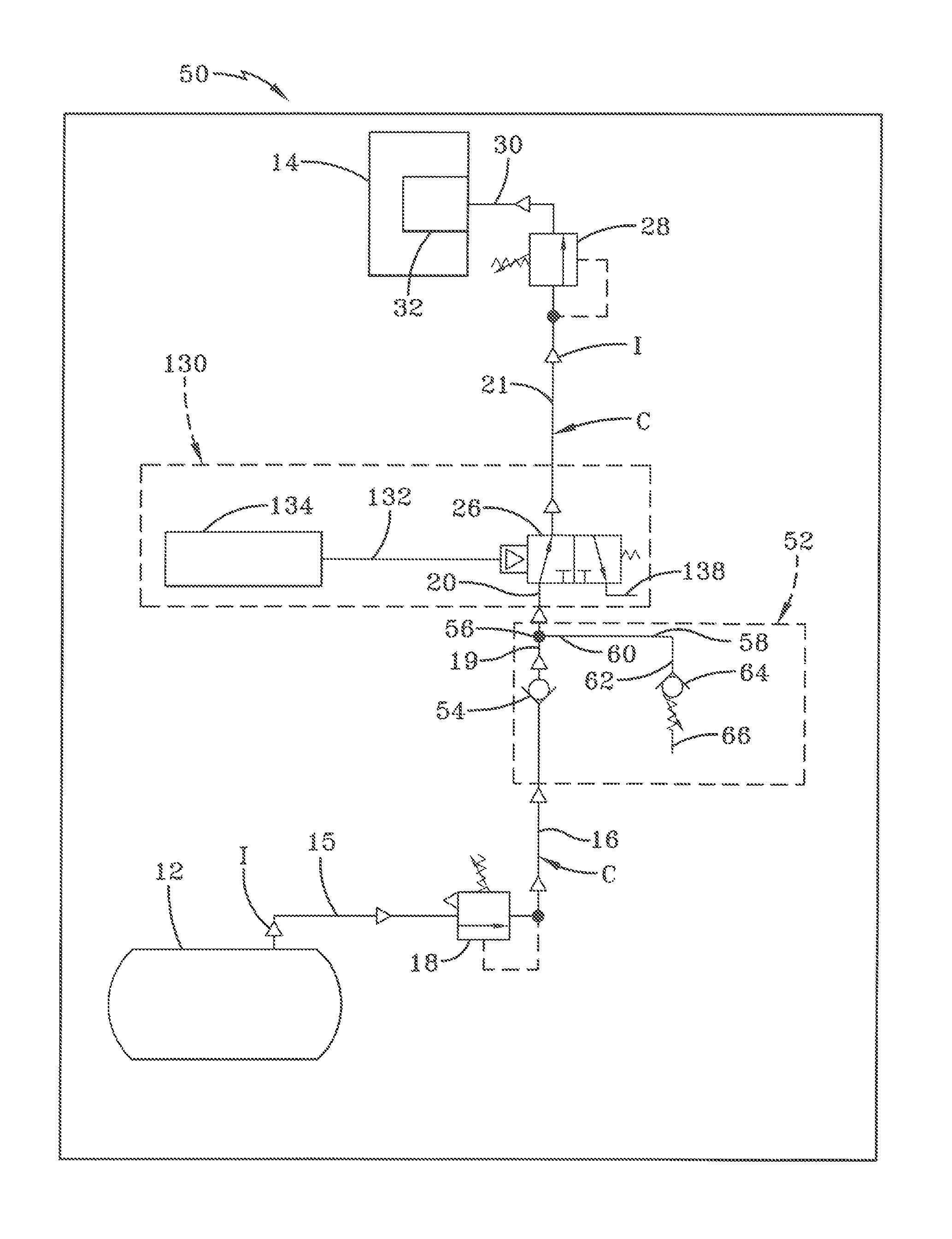
[0070]First check valve 54 of second embodiment tire inflation system 50 enables air to flow in the direction from supply tank 12 to tires 14, but prevents air from flowing in the opposite direction, that is, from the tires to the supply tank. Fourth pneumatic conduit section 19 is fluidly connected to and extends between first check valve 54 and a pneumatic fitting 56, which preferably is a tee fitting. Fifth pneumatic conduit section 20 is fluidly connected to and extends between tee fitting 56 and isolation valve 26 of optional tire isolation system 130.

[0071]Deflation circuit 52 further includes a deflation pneumatic conduit 58. Deflation pneumatic conduit 58 includes a first end 60 and a second end 62. First end 60 of deflation pneumatic conduit 58 is fluidly connected to tee fitting 56, which provides fluid communication between fifth pneumatic conduit section 20 and the deflation pneumatic conduit. Second end 62 of deflation pneumatic conduit 58 is fluidly connected to a seco...

third embodiment

[0089]It is to be understood that deflation circuit 72 of third embodiment tire inflation system 70 has been described with reference to the use of separate check valves 22, 40, tee fittings 34, 36, conduit sections 16, 17, 19, 20, 74a, 74b, 74c, and supply override valve 84 for the purposes of clear illustration of the invention. Preferably, check valves 22, 40 and / or supply override valve 84 are incorporated into a single or integrated valve body with corresponding passages in the valve body, thereby eliminating one or more of tee fittings 34, 36 and conduit sections 16, 17, 19, 20, 74a, 74b, 74c, without affecting the overall concept or operation of the invention. In addition, as described above, check valve 40 is biased to allow air to flow from the direction of tires 14 to supply tank 12 when the pneumatic pressure in second deflation pneumatic conduit section 74b is at least fixed differential X greater than the target pressure.

[0090]Preferably, rather than employing supply va...


PUM


Abstract

A vehicle tire inflation system includes an air supply source in fluid communication with multiple tires of the vehicle. A pneumatic conduit extends between and is in fluid communication with the air supply source and the tires. Means are fluidly connected to the pneumatic conduit for enabling selective inflation and deflation of the tires. The means include a first pneumatic circuit for inflation of the tires, and a second pneumatic circuit for deflation of the tires. The second pneumatic circuit is discrete from the first pneumatic circuit and is common to more than one of the tires. The means provides controlled deflation of the tires in the second pneumatic circuit based upon a predetermined condition, preventing deflation of the tires until the vehicle is parked, or limiting the deflation of the tires, which in turn enables the tire inflation system to accommodate a desirable increased pressure in the tires.

Description

CROSS-REFERENCE TO RELATED APPLICATIONS[0001]This application claims the benefit of U.S. Provisional Patent Application Ser. No. 61 / 369,159, which was filed on Jul. 30, 2010.BACKGROUND OF THE INVENTION[0002]1. Technical Field[0003]The invention relates to the art of tire inflation systems. More particularly, the invention relates to tire inflation systems for heavy-duty vehicles such as trucks and tractor-trailers or semi-trailers, which can operate as the vehicles are moving. Still more particularly, the invention is directed to a tire inflation system which includes a tire deflation circuit that is discrete or separate from an inflation Circuit, thereby enabling control of tire deflation based on specific predetermined conditions.[0004]2. Background Art[0005]Heavy-duty vehicles typically include trucks and tractor-trailers or semi-trailers. Tractor-trailers and semi-trailers, which shall collectively be referred to as tractor-trailers for the purpose of convenience, include at lea...

Claims


Application Information

Patent Timeline
Patent Type & Authority Patents(United States)
IPC IPC(8): B60C23/00
CPCB60C23/003B60C23/00B60C23/10B60C2200/06B60C23/00354B60C23/00372
Inventor WILSON, MATT J.CERVANTEZ, JESSE W.PADULA, SANTO
Owner HENDRICKSON USA L L C
Why Eureka
Try Eureka