Tire inflation system with discrete deflation circuit
a technology of deflation circuit and tire inflation system, which is applied in the direction of tire measurement, vehicle components, transportation and packaging, etc., can solve the problems of difficulty in manually checking and maintaining the target pressure for each and every tire, tire pressure might not be checked, and air may leakage from a tir
- Summary
- Abstract
- Description
- Claims
- Application Information
AI Technical Summary
Benefits of technology
Problems solved by technology
Method used
Image
Examples
first embodiment
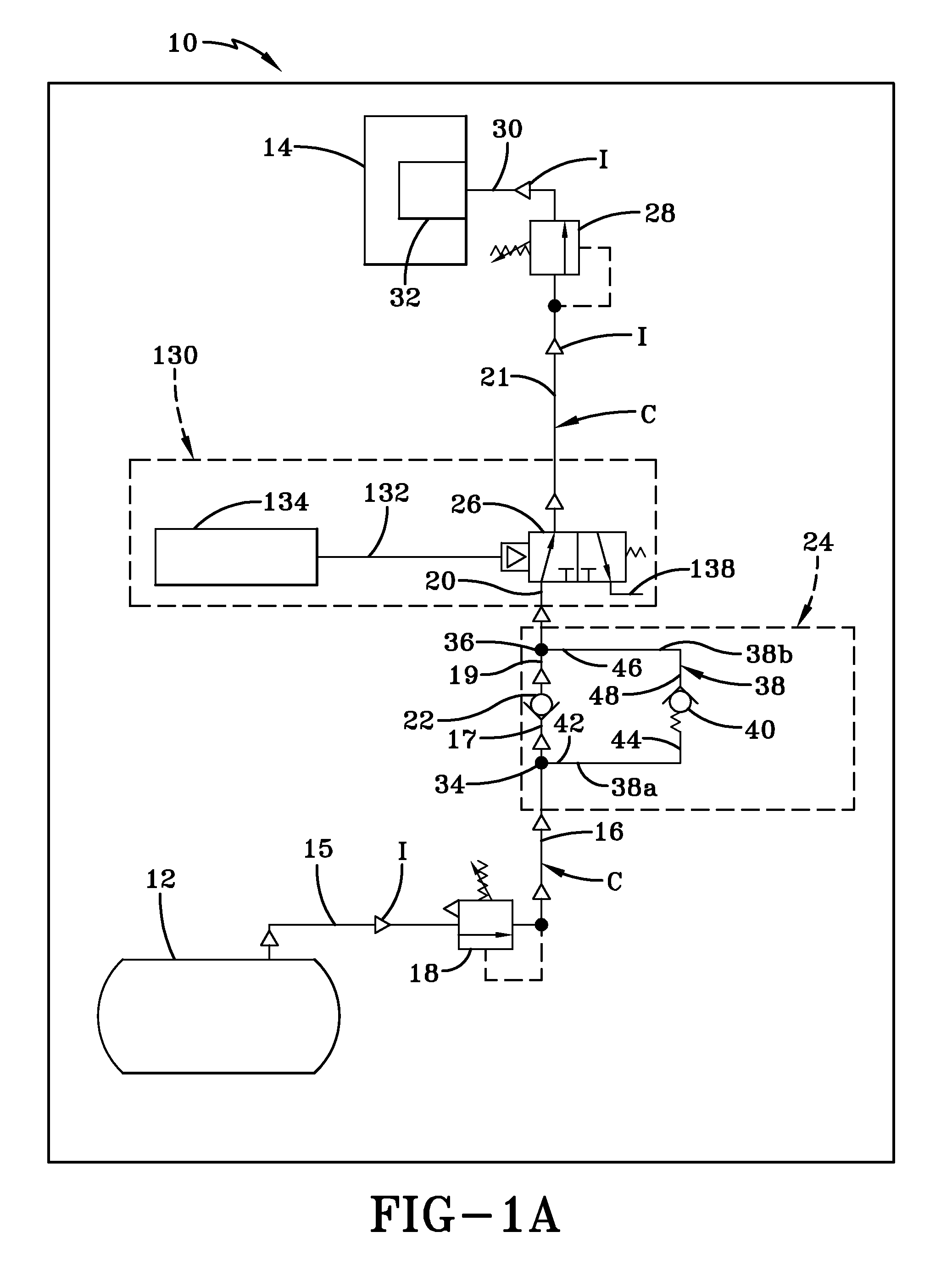
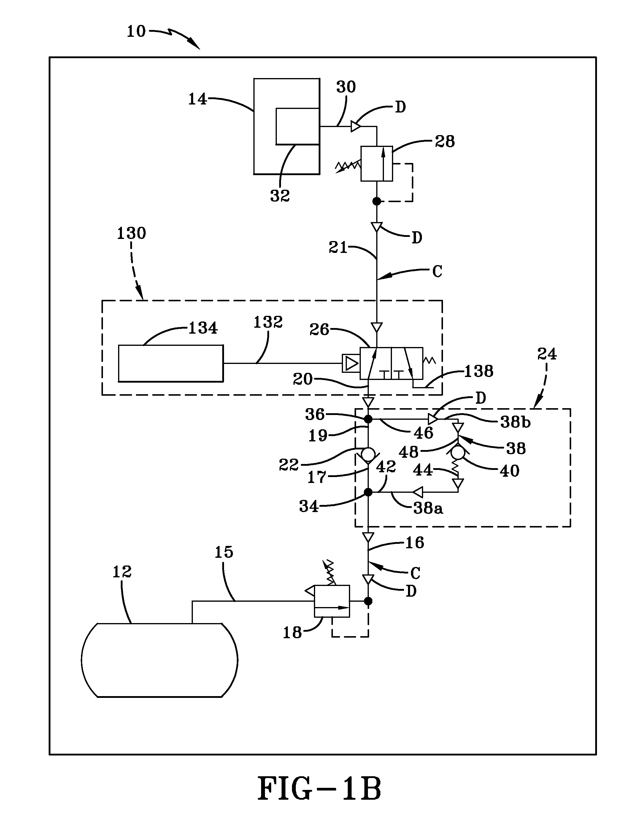
[0060]The desirable effect of the use of fixed differential X in deflation circuit 24 of first embodiment tire inflation system 10 is illustrated by the operation of the system. More particularly, as described above, the vehicle operator or a technician selects a target pressure by adjusting supply valve 18 using means that are placed in a convenient location inside the vehicle cab, or outside of the vehicle cab, such as on the trailer of a tractor-trailer, depending on system requirements. As shown in FIG. 1A, when inflation of tires 14 is required, supply valve 18 is opened or actuated, enabling air to flow from supply tank 12, through first pneumatic conduit section 15, through the supply valve and to second pneumatic conduit section 16, first tee fitting 34 of deflation circuit 24 and third pneumatic conduit section 17. First check valve 22 ensures that air continues to flow from third pneumatic conduit section 17 through fourth pneumatic conduit section 19 to second tee fitting...
second embodiment
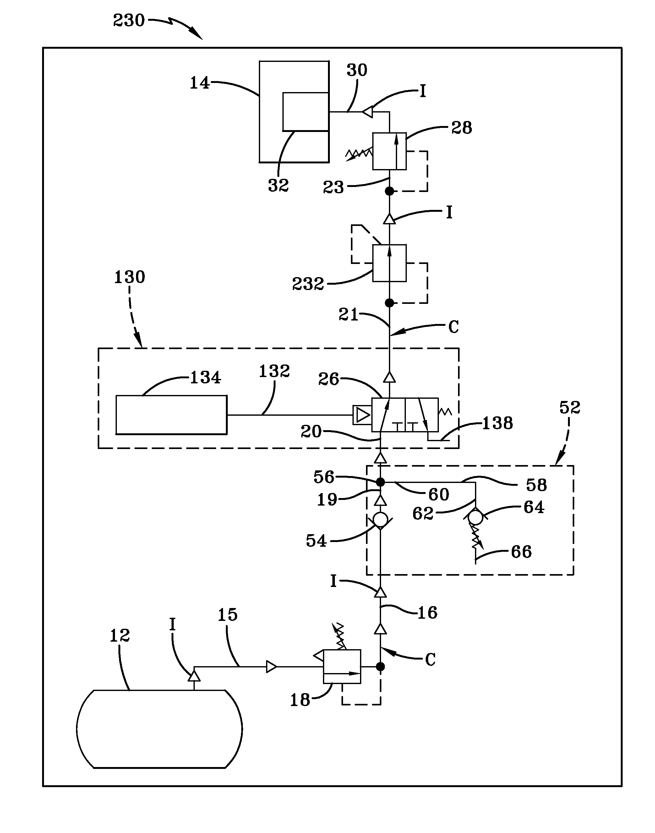
[0072]First check valve 54 of second embodiment tire inflation system 50 enables air to flow in the direction from supply tank 12 to tires 14, but prevents air from flowing in the opposite direction, that is, from the tires to the supply tank. Fourth pneumatic conduit section 19 is fluidly connected to and extends between first check valve 54 and a pneumatic fitting 56, which preferably is a tee fitting. Fifth pneumatic conduit section 20 is fluidly connected to and extends between tee fitting 56 and isolation valve 26 of optional tire isolation system 130.
[0073]Deflation circuit 52 further includes a deflation pneumatic conduit 58. Deflation pneumatic conduit 58 includes a first end 60 and a second end 62. First end 60 of deflation pneumatic conduit 58 is fluidly connected to tee fitting 56, which provides fluid communication between fifth pneumatic conduit section 20 and the deflation pneumatic conduit. Second end 62 of deflation pneumatic conduit 58 is fluidly connected to a seco...
third embodiment
[0091]It is to be understood that deflation circuit 72 of third embodiment tire inflation system 70 has been described with reference to the use of separate check valves 22, 40, tee fittings 34, 36, conduit sections 16, 17, 19, 20, 74a, 74b, 74c, and supply override valve 84 for the purposes of clear illustration of the invention. Preferably, check valves 22, 40 and / or supply override valve 84 are incorporated into a single or integrated valve body with corresponding passages in the valve body, thereby eliminating one or more of tee fittings 34, 36 and conduit sections 16, 17, 19, 20, 74a, 74b, 74c, without affecting the overall concept or operation of the invention. In addition, as described above, check valve 40 is biased to allow air to flow from the direction of tires 14 to supply tank 12 when the pneumatic pressure in second deflation pneumatic conduit section 74b is at least fixed differential X greater than the target pressure.
[0092]Preferably, rather than employing supply va...
PUM
 Abstract
Description
Claims
Application Information
 - R&D
- Intellectual Property
- Life Sciences
- Materials
- Tech Scout
- Unparalleled Data Quality
- Higher Quality Content
- 60% Fewer Hallucinations
Browse by: Latest US Patents, China's latest patents, Technical Efficacy Thesaurus, Application Domain, Technology Topic, Popular Technical Reports.
© 2025 PatSnap. All rights reserved.Legal|Privacy policy|Modern Slavery Act Transparency Statement|Sitemap|About US| Contact US: help@patsnap.com


