Diffuser for terrestrial or aviation gas turbine

a technology for diffusers and gas turbine engines, applied in the direction of gas turbine plants, hot gas positive displacement engine plants, machines/engines, etc., can solve the problems of affecting the efficiency of the diffuser, the risk of boundary layer thickening, and the loss of pressure in the exhaust casing, so as to reduce the drawbacks of pressure loss and mitigate the effect of such drawbacks

Inactive Publication Date: 2003-07-24
SN DETUDE & DE CONSTR DE MOTEURS DAVIATION S N E C M A
View PDF6 Cites 21 Cited by
  • Summary
  • Abstract
  • Description
  • Claims
  • Application Information

AI Technical Summary

Benefits of technology

0005] The present invention thus seeks to mitigate such drawbacks by prop...

Problems solved by technology

An exhaust casing suffers from pressure losses which are typically proportional to the square of the speed of the gas at the leading edge of the casing arms.
The slope of the walls constituting the diffuser must not exceed a certain value since otherwise there is a risk of boundary layers on said walls ...

Method used


Image

  • Diffuser for terrestrial or aviation gas turbine
  • Diffuser for terrestrial or aviation gas turbine
  • Diffuser for terrestrial or aviation gas turbine

Examples


Embodiment Construction

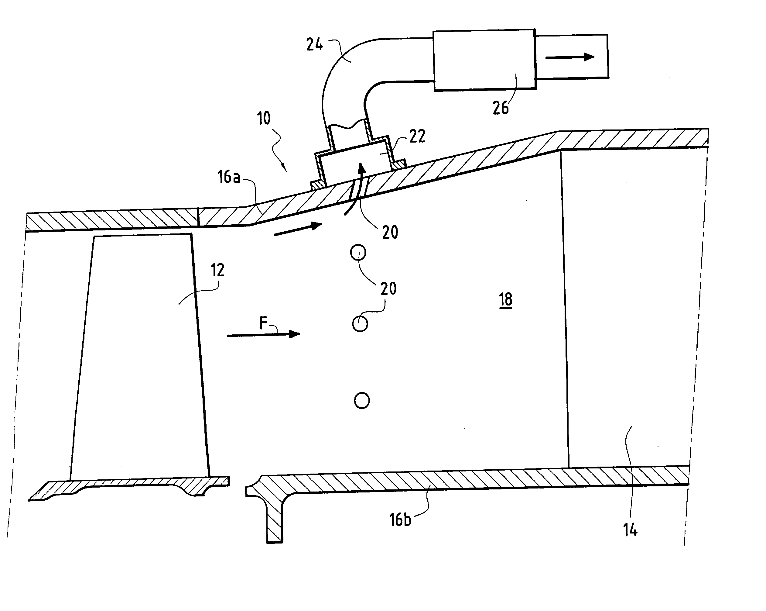
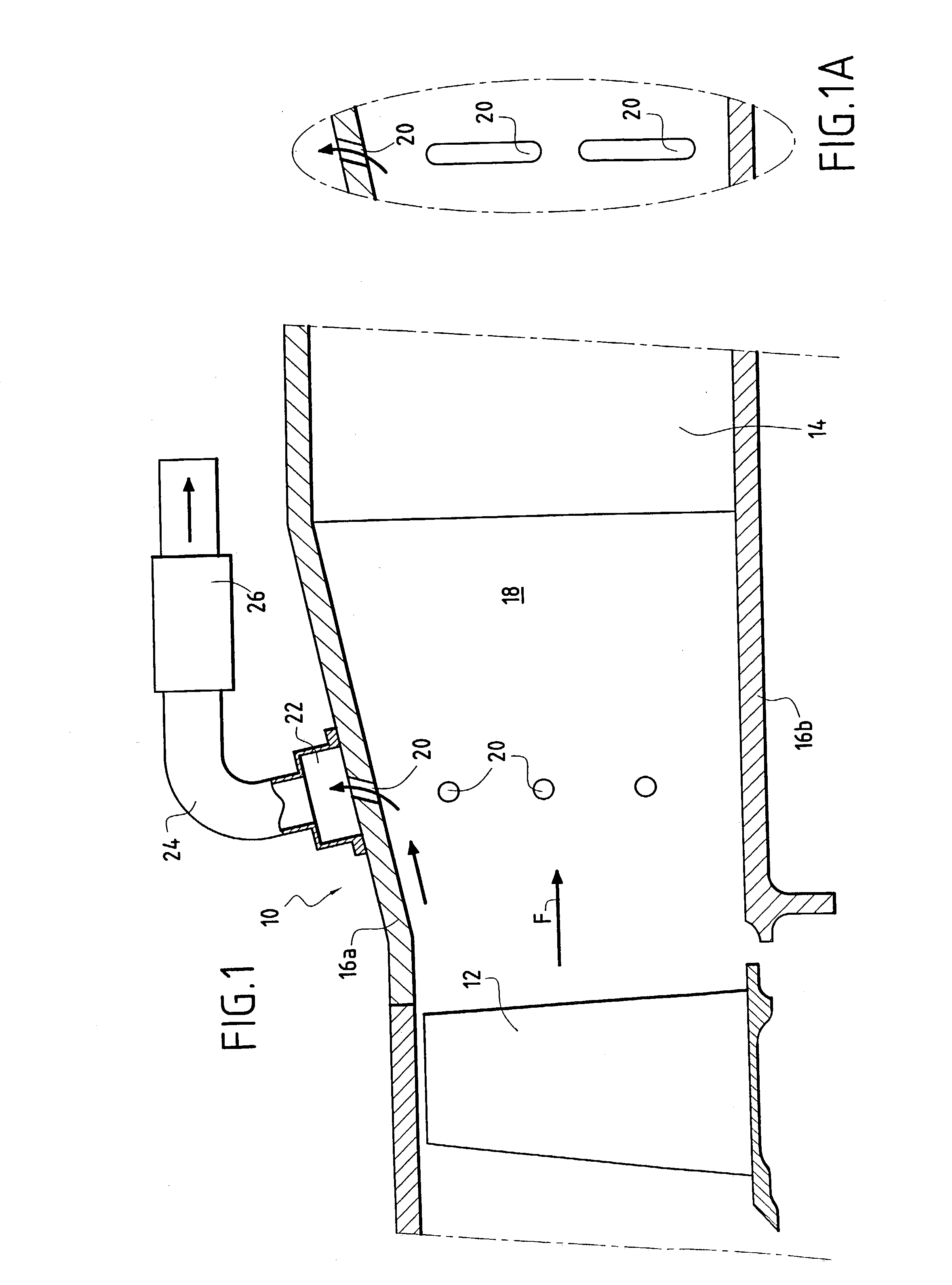
[0013] In FIG. 1, there can be seen a diffuser 10 disposed immediately downstream from a moving wheel 12 of a last stage of a gas turbine, where "downstream" is in the flow direction of a gaseous fluid coming from said turbine and marked by arrow F. A casing arm 14 serving in particular to straighten the gas flow is mounted downstream from the diffuser 10.

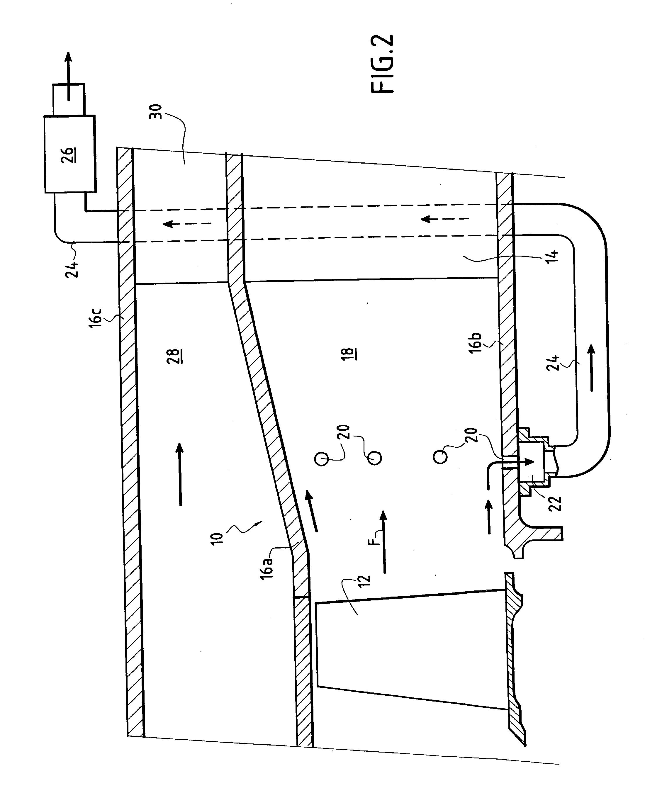
[0014] The diffuser 10 has an outer annular wall 16a and an inner annular wall 16b so as to form an annular passage 18 for the gas from the turbine. The walls 16a and 16b are arranged in such a manner that the annular passage 18 diverges in the gas flow direction F so as to reduce the flow speed and increase the pressure of the gas passing therethrough. The outer wall 16a diverges while the inner wall 16b is substantially parallel to the axis (not shown) of the engine fitted with this diffuser. It is also possible to devise a diffuser in which the inner wall 16b diverges (relative to the fluid) while the outer wall 16a is parallel ...


PUM


Abstract

A diffuser for a gas turbine engine, said diffuser being disposed between a last stage of a turbine and an exhaust casing, and comprising an outer annular wall and an inner annular wall together defining an annular passage for fluid that diverges in the flow direction of said fluid, at least one of the annular walls including a plurality of orifices leading from said annular passage to at least one collecting box leading to means for exhausting a fraction of said fluid so as to reduce the flow speed of said fluid in said annular passage.

Description

[0001] The present invention relates to the general field of diffusers for gas turbine engines of terrestrial or aviation type. It relates more particularly to diffusers placed between the turbine and the exhaust casing of a gas turbine engine.[0002] The function of terrestrial or aviation gas turbines is to deliver power that is sufficient to drive either an alternator (terrestrial turbines) or a compressor (aviation turbines). To do this, a gas turbine takes a fraction of the energy of the hot compressed gases coming from the combustion chamber of the turbine engine and transforms it into mechanical energy. A turbine generally comprises a plurality of stages, each stage comprising a stator nozzle and a moving wheel placed after the nozzle for accelerating the flow of gas. The gas coming from the last stage of the turbine then feeds an exhaust casing.[0003] The exhaust casing placed immediately downstream from the turbine is constituted by a diffuser and by casing arms which serve ...

Claims


Application Information

Patent Timeline
IPC IPC(8): F01D25/30
CPCF01D25/30
Inventor NOTTIN, CLAUDE
Owner SN DETUDE & DE CONSTR DE MOTEURS DAVIATION S N E C M A
Why Eureka
Try Eureka