
Cooling structure for environmental-friendly vehicle

a technology of cooling structure and vehicle, applied in the direction of electric propulsion mounting, electric generators, transportation and packaging, etc., can solve the problems of affecting the merchantability of environmental-friendly vehicles, consuming precious interior space, and batteries releasing significant heat, so as to effectively cool down the battery and reduce the pressure drop depending on the air flow inside the duct. , the effect of improving cooling performan

Active Publication Date: 2014-08-05
HYUNDAI MOTOR CO LTD +1
View PDF14 Cites 21 Cited by
  • Summary
  • Abstract
  • Description
  • Claims
  • Application Information

AI Technical Summary

Benefits of technology

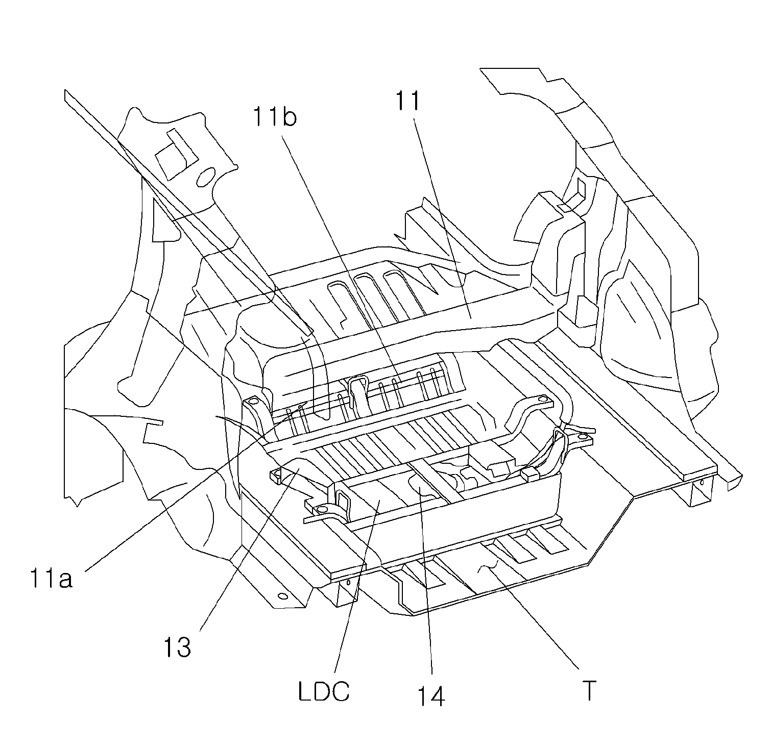
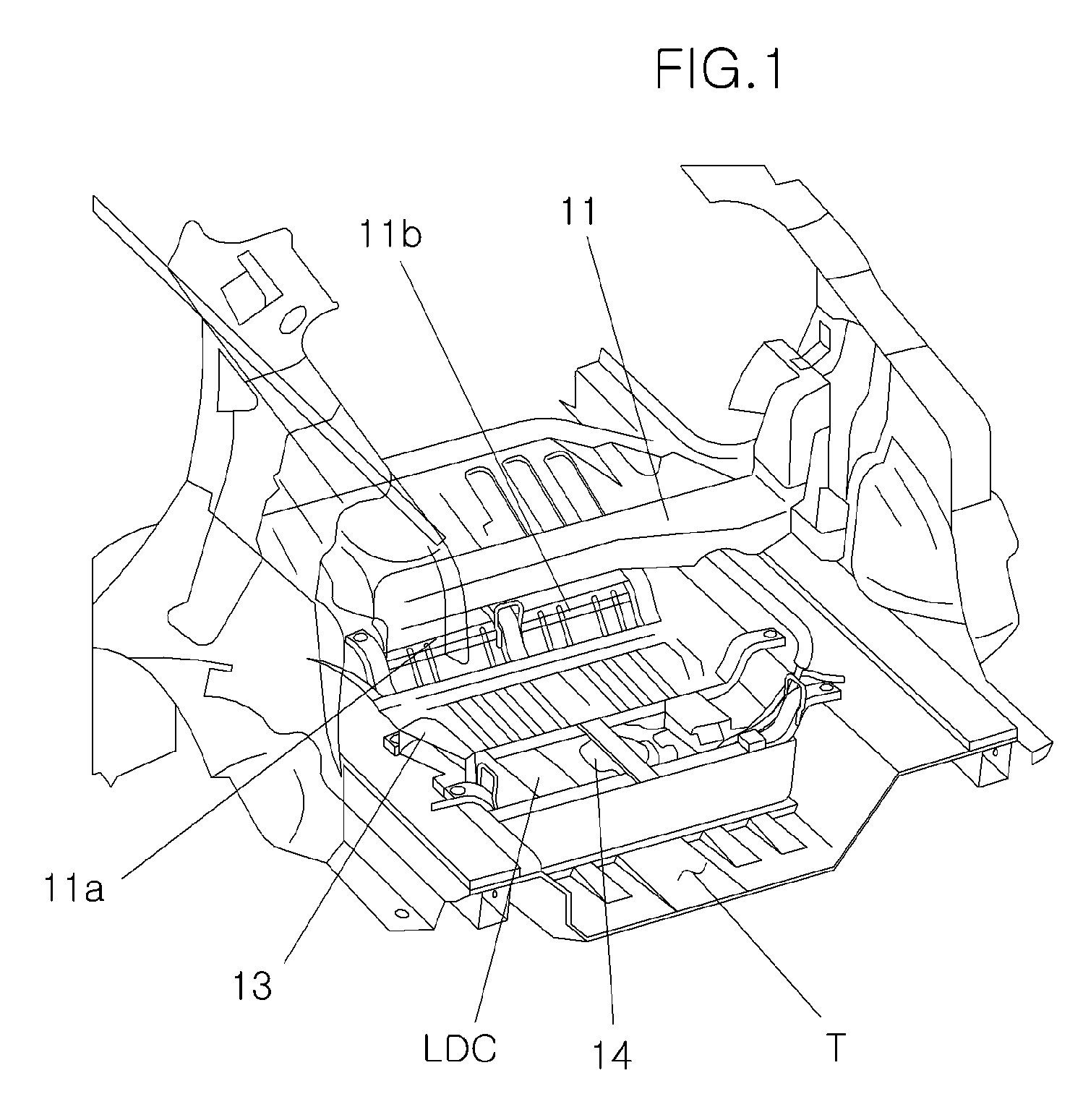
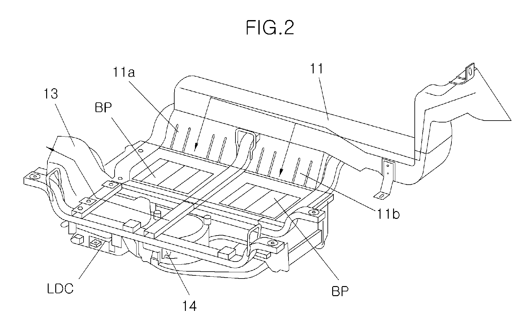
The present invention provides a cooling structure for an environmental-friendly vehicle that uses multiple battery packs arranged in a tire well to minimize pressure loss and improve cooling performance. The cooling air is divided and sent over the battery packs through separate flow paths, allowing for effective cooling without temperature increase. This structure design also reduces the space required for battery installation, increasing the interior space of the vehicle, and absorbing impulses during rear-end collisions to ensure safety.

Problems solved by technology

Since the battery is mounted inside the environmental-friendly vehicle, the mounting position of the battery often takes up precious an interior space and thus the merchantable quality of the environmental-friendly vehicle is typically affected as a result.
In addition to taking up space, these batteries emit a significant amount of heat while being operated.
In most cases, however, the battery cooling structure only include a duct for guiding air flow and a cooling fan for forcing or accelerating the air flow.
Thus, the conventional cooling structures do not effective cool the batteries in these types of vehicles.

Method used


Image

  • Cooling structure for environmental-friendly vehicle
  • Cooling structure for environmental-friendly vehicle
  • Cooling structure for environmental-friendly vehicle

Examples


Embodiment Construction

[0023]Reference will now be made in detail to various embodiments of the present invention(s), examples of which are illustrated in the accompanying drawings and described below. While the invention(s) will be described in conjunction with exemplary embodiments, it will be understood that present description is not intended to limit the invention(s) to those exemplary embodiments. On the contrary, the invention(s) is / are intended to cover not only the exemplary embodiments, but also various alternatives, modifications, equivalents and other embodiments, which may be included within the spirit and scope of the invention as defined by the appended claims.

[0024]It is understood that the term “vehicle” or “vehicular” or other similar term as used herein is inclusive of motor vehicles in general such as passenger automobiles including sports utility vehicles (SUV), buses, trucks, various commercial vehicles, watercraft including a variety of boats and ships, aircraft, and the like, and i...


PUM


Abstract

Disclosed is a battery cooling structure for an environmental-friendly vehicle. The battery cooling structure for the environmental-friendly vehicle includes a plurality of battery packs that supply power to a motor and are arranged in parallel so as to be spaced a predetermined distance from each other inside a tire well. An inflow duct is disposed to provide fluid communication and connection with the interior of the vehicle so that the air inside the vehicle is sucked into the inflow duct. A plurality of diverging ducts independently supply the air to the respective battery packs which are arranged and spaced a predetermined distance from each other on the downstream side of the inflow duct. A lower duct is disposed under the battery pack and joins diverging air flows, and a cooling fan is disposed on downstream side of the lower duct and is configured to discharge the air to the outside.

Description

CROSS-REFERENCE TO RELATED APPLICATIONS[0001]The present application claims priority to Korean Patent Application Number 10-2011-0058536 filed Jun. 16, 2011, the entire contents of which application is incorporated herein for all purposes by this reference.BACKGROUND OF THE INVENTION[0002]1. Field of the Invention[0003]The present invention relates to a cooling structure for an environmental-friendly vehicle, and more particularly, to a cooling structure for an environmental-friendly vehicle which has a battery mounted in a tire well of a trunk thereof and supplies diverging cooling air to cool down the battery.[0004]2. Description of Related Art[0005]Environmentally-friendly vehicles such as electric vehicle or hybrid vehicles utilize a high voltage battery mounted therein to supply power to a motor serving as a power source thereof. Since the battery is mounted inside the environmental-friendly vehicle, the mounting position of the battery often takes up precious an interior space...

Claims


Application Information

Patent Timeline
Patent Type & Authority Patents(United States)
IPC IPC(8): B60K1/04B60K11/06B62D25/08B62D25/20
CPCB60K1/04B60K11/06B60K2001/005B60K2001/0416B60K2001/045Y02E60/10H01M10/613H01M10/625H01M10/6563
Inventor LIM, HAEKYUJEON, YOONCHEOLLEE, YONGJIN
Owner HYUNDAI MOTOR CO LTD
Learn More