Fluidized bed apparatus having spray chamber with pivotal slats

a technology of pivotal slats and flue bed, which is applied in the direction of drying machines, lighting and heating apparatus, furnaces, etc., can solve the problems of affecting the nozzle arm structure, and reducing the service life of the nozzle arm

Inactive Publication Date: 2001-03-20
HENKEL KGAA
View PDF11 Cites 5 Cited by
  • Summary
  • Abstract
  • Description
  • Claims
  • Application Information

AI Technical Summary

Problems solved by technology

However, it has disadvantages where the materials to be granulated are molten because the relatively large distance from the nozzles to the fluidized bed leads to premature cooling and hence to solidification of the melt.
However, the flexibility of the nozzle lines lying within the entry chamber necessitated by the pivotability of the slats leads to the disadvantages discussed hereinafter.
In the known fluidized bed apparatus, the necessary, structurally complex rotatability of the nozzle arm requires a flexible feed line, for example a hose, for the liquid to be sprayed.
If melts are to be sprayed, problems arise as, for example, in the case of molten nonionic surfactants.
Accordingly, heating of the feed line is generally unavoidable.
In the case of a flexible and pivotal feed line for the melt to be sprayed, these requirements lead to major design problems.
If, for example, electrically heated, externally insulated hoses are used in the flexible feed line, the internal hose undergoes thermal expansion after a short period of operation, resulting in inadequate heating and insulation.
Another disadvantage of the prior art as represented by EP 0 370 167 B1 is that, when the slats are moved from their oblique to their horizontal position and vice versa, the four nozzle arms also have to be swung downwards and upwards, respectively.

Method used


Image

  • Fluidized bed apparatus having spray chamber with pivotal slats
  • Fluidized bed apparatus having spray chamber with pivotal slats
  • Fluidized bed apparatus having spray chamber with pivotal slats

Examples


Embodiment Construction

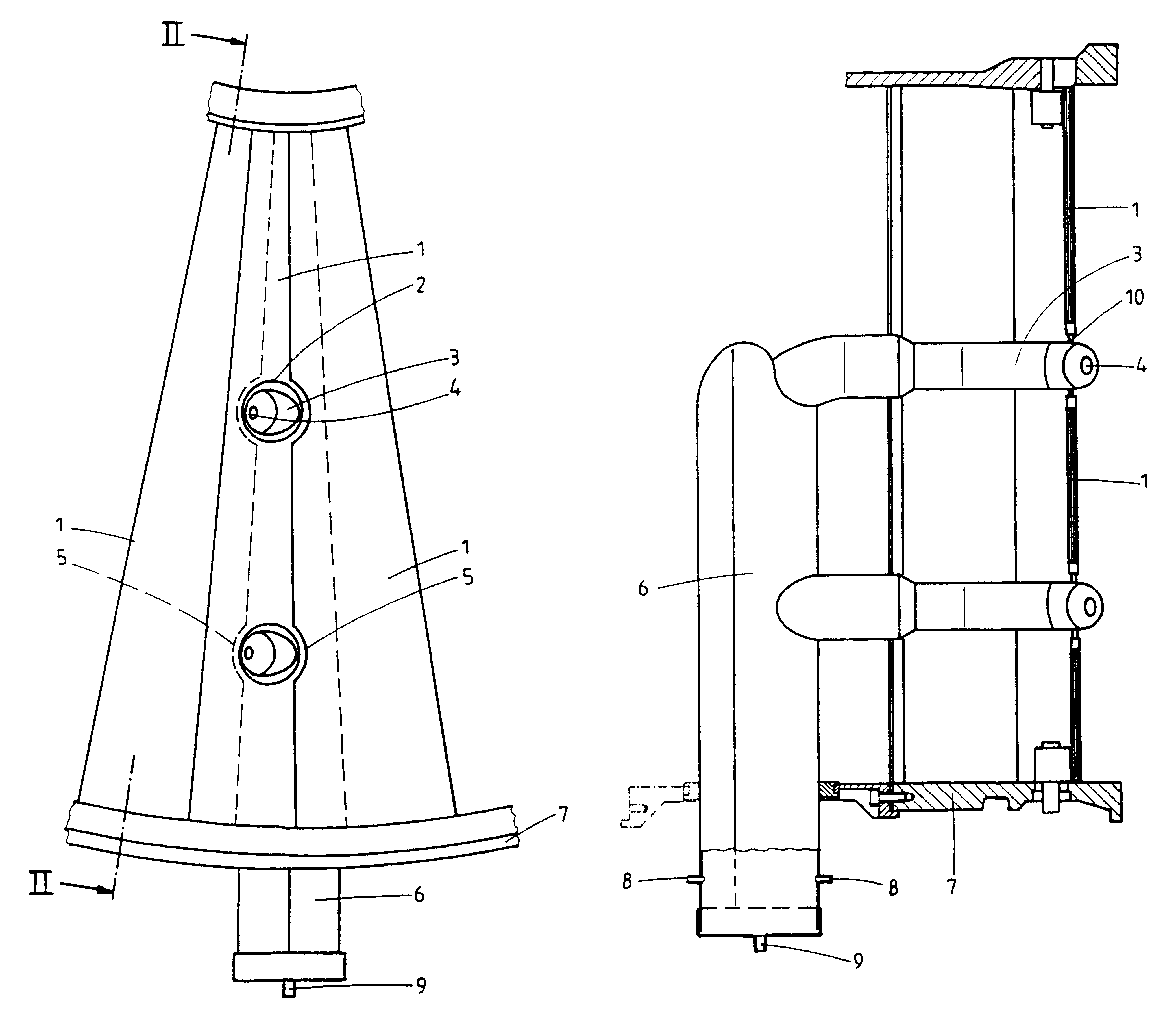
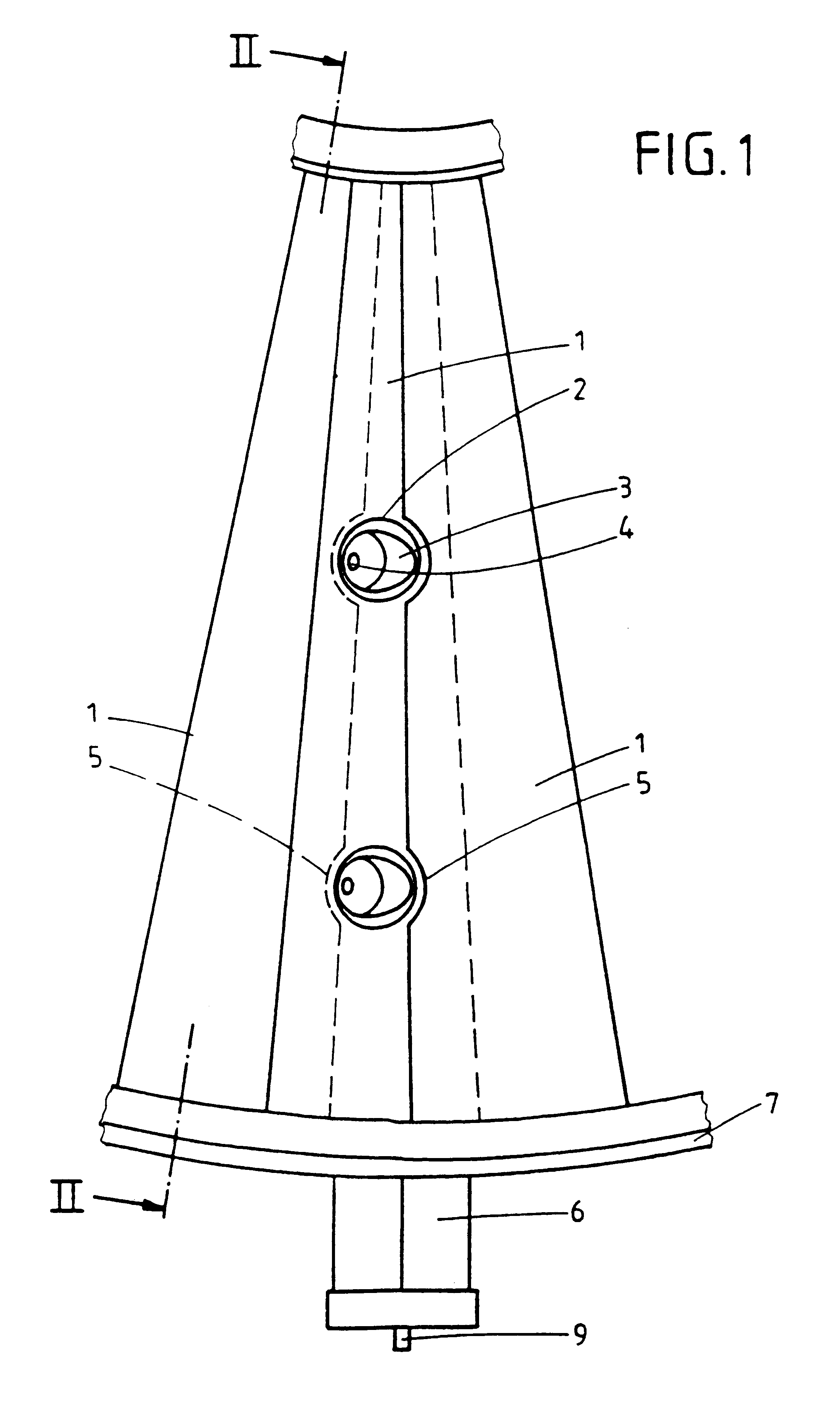
The problem addressed by the present invention was to avoid the above-mentioned disadvantages arising out of the pivotability of the slats in a fluidized bed apparatus of the type mentioned at the beginning in a simple and economic manner.

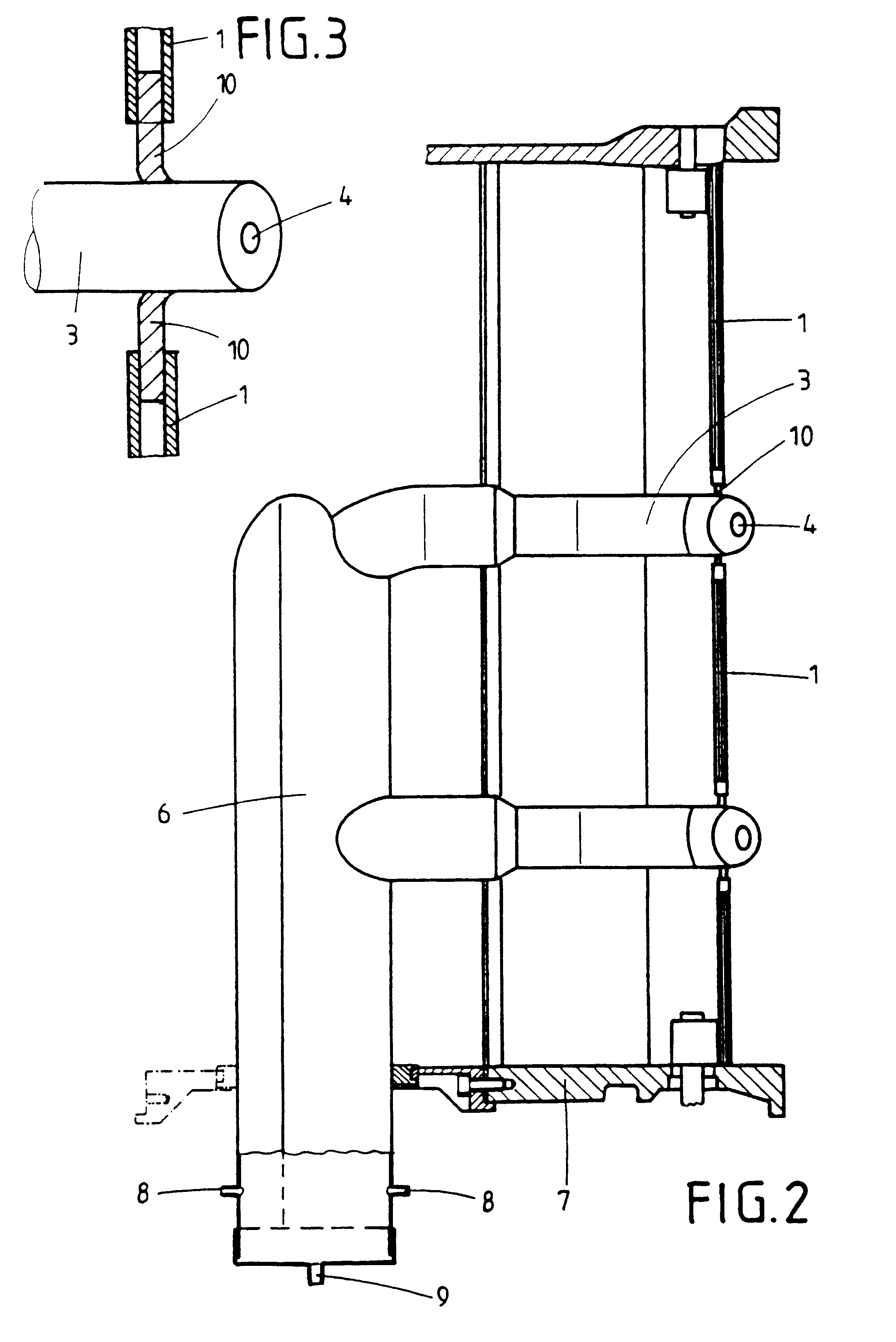
According to the invention, the solution to this problem is characterized in that the slats have cutouts through which the nozzle lines are guided so that they extend partly into the fluidization chamber, the cutouts being sufficiently large for the pivoting movement of the slats.

The cutouts are preferably sealed off from the nozzle lines by a flexible material. However, sealing is not absolutely essential provided that an adequate flow of air from the entry chamber into the fluidized bed chamber ensures that the granules do not drop through the cutouts.

According to the invention, nozzle arms rigidly arranged in the fluidized bed apparatus with non-flexible nozzle lines may be used so that the design of the heating, thermal insulation and cooling s...


PUM

PropertyMeasurementUnit
temperatureaaaaaaaaaa
melting temperatureaaaaaaaaaa
temperatureaaaaaaaaaa

Abstract

A fluidized bed apparatus for the production and treatment of granules and a method for its operation is provided. The fluidized bed apparatus includes an entry chamber through which a gas is designed to flow upwards; a fluidization chamber for fluidizing the material located above the entry chamber; pivotal slats located between the entry chamber and the fluidization chamber; and a nozzle arm located in the chamber below the slats with a nozzle line ending in a nozzle which is directed into the fluidization chamber through cutouts in the slats and extends partly into the fluidization chamber. The fluidized bed apparatus has rigid nozzle arms and lines which are easily jacketed for heating and cooling applications.

Description

1. Background of the InventionThis invention relates to a fluidized bed apparatus for the production and / or further treatment of granules comprisinga container with an entry chamber through which a gas, especially air, is designed to flow upwards and a fluidization chamber for fluidizing the material located above the entry chamber;pivotal slats disposed between the entry chamber and the fluidization chamber andat least one nozzle arm disposed in the container below the slats and having at least one nozzle line which carries a nozzle directed into the fluidization chamber for introducing materials to be granulated.The fluidized bed apparatus according to the invention is also intended to be suitable in particular for coating temperature-sensitive granules, for example enzymes, by spraying on molten material.2. Discussion of Related ArtIt is known that materials to be granulated can be introduced into the fluidized bed of a fluidized bed apparatus by various nozzle arrangements throu...

Claims


Application Information

Patent Timeline
Patent Type & Authority Patents(United States)
IPC IPC(8): B01J2/16B05B7/14B01J8/38B01J8/44
CPCB01J2/16
Inventor PAATZ, KATHLEENPICHLER, WERNERRAEHSE, WILFRIEDRAKER, HANS
Owner HENKEL KGAA
Why Eureka
Try Eureka