Rotary cutting tool

a cutting tool and rotary technology, applied in the field of rotary cutting tools and end mills, can solve the problems of shock resistance, vibration along with heat and wear resistance, and the inability to address satisfactorily the concern of resonant vibration or shock resistance, so as to reduce, if not eliminate, the resonant vibration. , the effect of excellent cutting operation

Active Publication Date: 2006-01-31
NIAGARA CUTTER LLC
View PDF13 Cites 119 Cited by
  • Summary
  • Abstract
  • Description
  • Claims
  • Application Information

AI Technical Summary

Benefits of technology

[0025]It is an object of the present invention to provide an economically viable, improved rotary cutting tool that provides an excellent cutting operation with smooth surfaces. A principal objective of the present invention also is to provide vibration-free operability of a rotary cutting tool. Therefore, the core focus of the present invention is to provide a rotary cutting tool that significantly reduces, if not eliminates, the resonant vibration.
[0026]In order to achieve these objectives, the present invention studied the mechanism in material cutting in conjunction with the principles of a stabilizing technology. Based on such studies, the inventor conceived the present invention to reduce and perhaps eliminate resonant vibration by making the rotary cutting tool unbalanced and therefore unsynchronized with respect to the cutting forces.
[0027]According to the present invention, a rotary cutter can reduce the resonant vibration generated by each flute by varying the circumferencial index of each flute whereby the flutes become asymmetric and unequal with each other. Additional stability is achieved by taking an unequal circumferencial index of the configuration and adding a second variable of an unequal helix angle to it. Even further stability is achieved by taking an unequal circumferencial index of the configuration, an unequal helix angle of the configuration, and adding a third variable of an unequal cutting edge rake angle to it. Further still, additional stability is achieved by taking an unequal circumferencial index of the configuration, an unequal helix angle of the configuration, an unequal cutting edge rake angle of the configuration, and adding a forth variable of an unequal cutting edge relief angle to it. Thus, the first embodiment of the present invention may generally be characterized as a rotary cutting tool embracing an unequal circumferencial index, and unequal flute helix, an unequal cutting edge rake, and an unequal cutting edge relief wherein all aspects, in regards to the angles to each element, are differentiated from one another by at least one half or more of a degree. The second embodiment may generally be characterized as a cutting tool that provides a superior stability by making all aspects of the cutting tool variable. In this embodiment, every cutting edge that has a helix, a rake, and a relief varies for the entire length of the cutting edge. The third embodiment may be generally characterized as a cutting tool whose end or side cutting edges have an unequal cutting edge rake and an unequal cutting edge relief differentiated from one another by at least one half or more of a degree. This additional configuration over the first or second embodiment allows greater stability during plunge or side cutting. The fourth embodiment may generally be characterized as a cutting tool whose end or side cutting edges are of a contoured shape and having an unequal cutting edge rake and an unequal cutting edge relief differentiated from one another by at least one-half or more degrees. This improvisation over the first or second embodiment allows greater stability during plunge, ramping, or contour cutting.
[0028]The present invention offers one or more of these desired results. The rotary cutting tool, according to the present invention, is a tool that is much more stable than ever before while offering an excellent cutting performance, a good surface finish and a greater cutting speed. At the same time, it leads to less chattering and a shorter downtime, all leading to a long tool life. Accordingly, it is a primary object of the present invention is to greatly reduce, if not completely eliminate, all resonant vibrations that may typically generate at higher cutting speeds.

Problems solved by technology

Resonant vibrations result in shock resistance.
Such vibrations along with heat and wear resistances are detrimental to a long tool life.
However, the concern involving resonant vibration or shock resistance is yet to be addressed satisfactorily.

Method used


Image

  • Rotary cutting tool
  • Rotary cutting tool
  • Rotary cutting tool

Examples


first embodiment

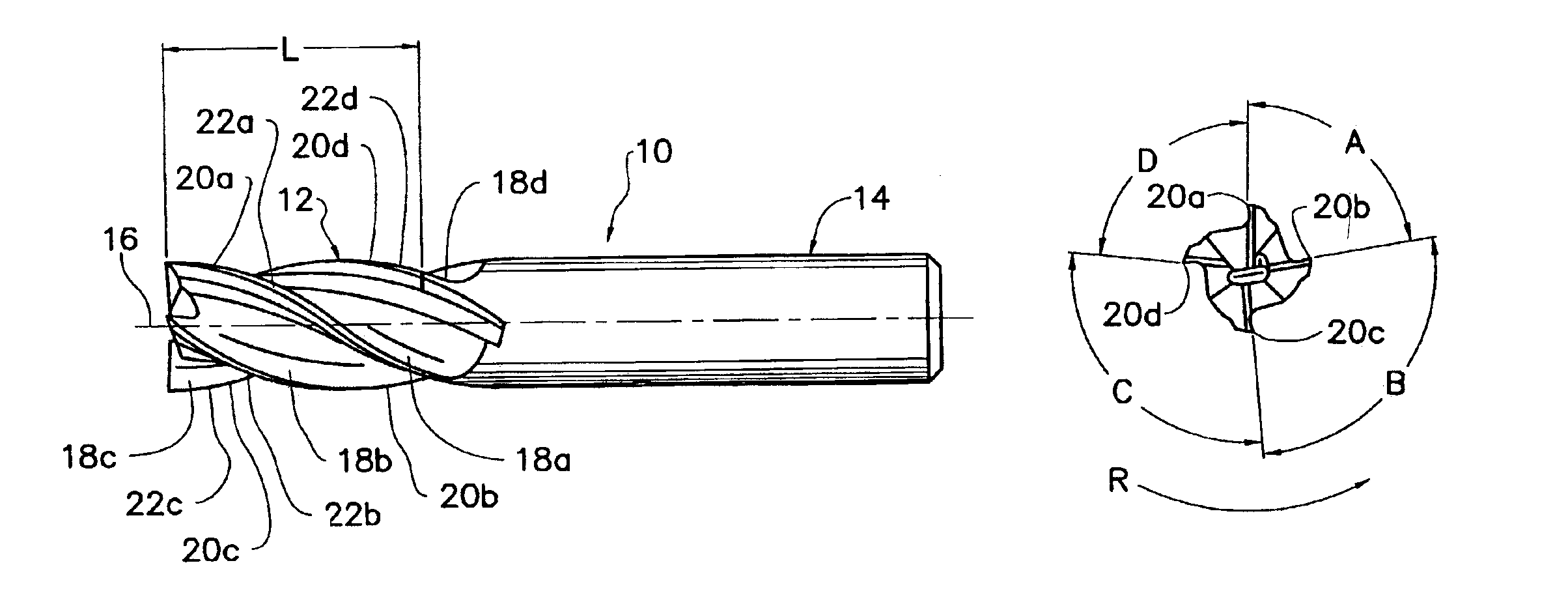
[0072]FIGS. 1 through 7 show a four-flute end mill in accordance with the present invention.

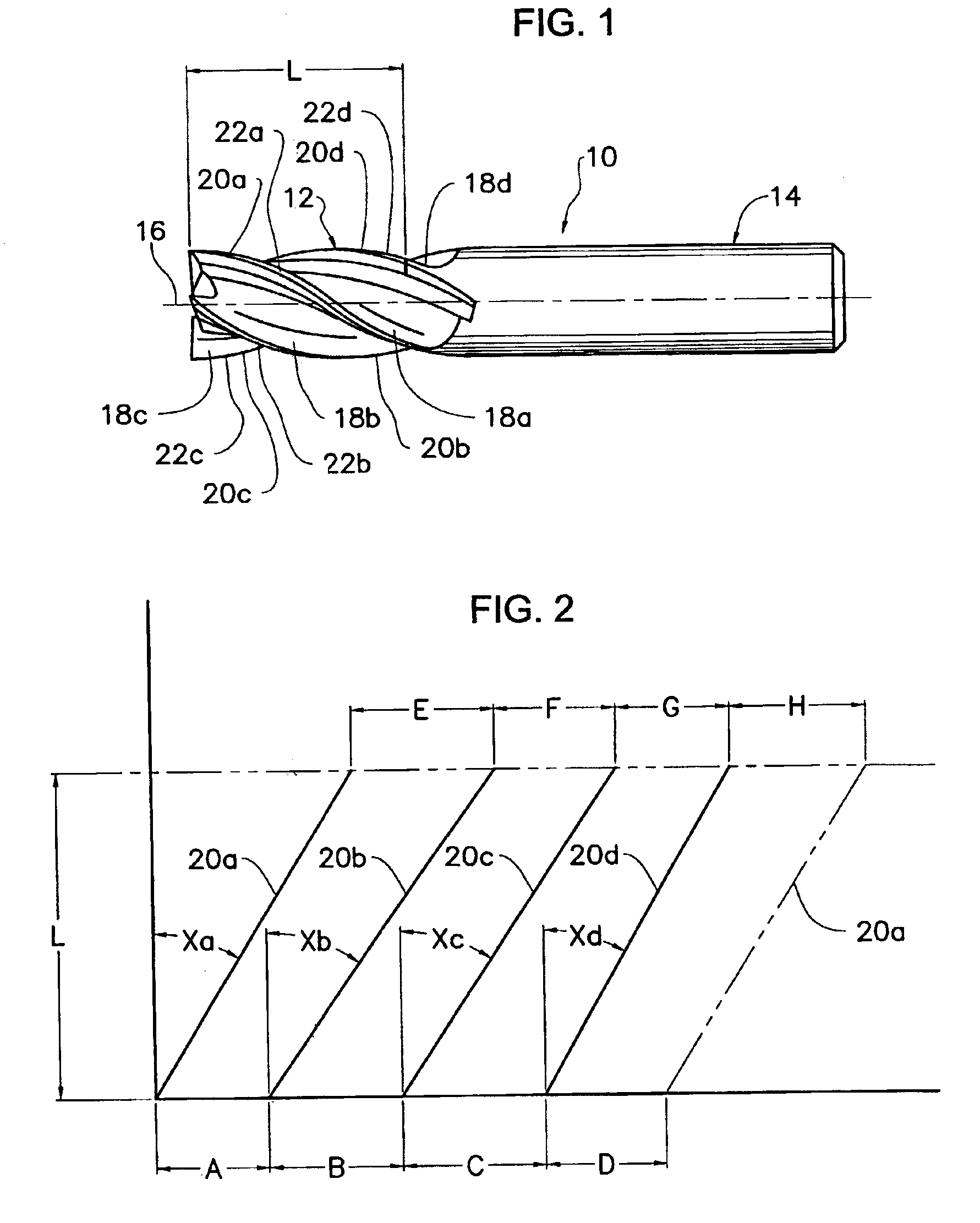
[0073]FIG. 1 shows an end mill 10 that includes: a cutting body 12; a shank 14; four radial cutting edges (20a, 20b, 20c, and 20d); four radial rake faces (18a, 18b, 18c, and 18d); four radial relief faces (22a, 22b, 22c, and 22d); a cutting length L; and a rotational axis 16. The cutting body 12 may be made of high speed steel, cemented carbide, cermet, or any other material or combination of materials that can be used to make rotary cutting tools.

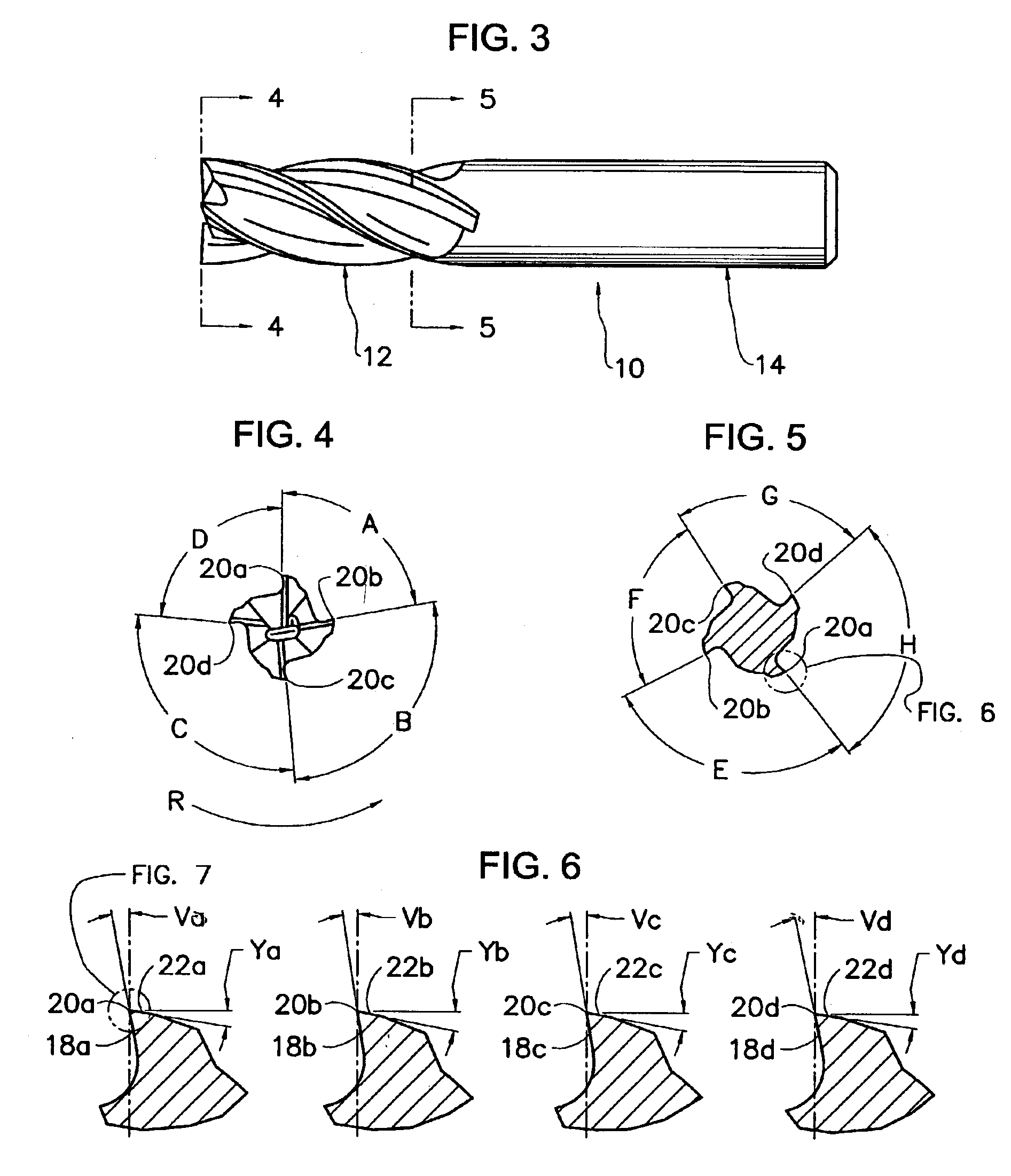
[0074]FIG. 2 shows the schematic view of the circumference of the cutting body 12. In this schematic view it is shown across the cutting length L that: the radial cutting edge 20a has a helix angle of Xa, a circumferencial index difference of angle A in relation to radial cutting edge 20b at the front of the cutting body 12 and a circumferencial index difference of angle E in relation to radial cutting edge 20b at the back of the cutting body 12; t...

third embodiment

[0094]FIGS. 16 through 19 show a modified four-flute end mill in accordance with the present invention, that being the addition variation of the axial cutting edges (26a, 26b, 26c, and 26d).

[0095]FIG. 16 shows a modified end mill 10 the same as FIG. 9 that includes: a cutting body 12 and a shank 14. This illustration is used to locate an end view of the axial cutting teeth for FIG. 17 and the enlarged side view of the axial cutting edges for FIG. 18, to explain the addition variation of the axial cutting edges (26a, 26b, 26c, and 26d).

[0096]FIG. 17 shows the end view of the cutting body 12 in FIG. 16 taken along the line 17—17 of FIG. 16 that includes: four radial cutting edges (20a, 20b, 20c, and 20d); four axial cutting edges (26a, 26b, 26c, and 26d); four axial rake faces (24a, 24b, 24c, and 24d); four axial relief faces (28a, 28b, 28c, and 28d).

[0097]FIG. 18 shows the enlarged fragmentary side view of the cutting body 12 in FIG. 16 taken from the view of FIG. 16 that includes: t...


PUM


Abstract

A rotary cutting tool that includes an elongated tool body, rotatable along a longitudinal axis of rotation is disclosed. It has a fluted cutting end on one end and a shank end on the opposite end of the tool body. The fluted cutting end includes a nose, a periphery and an end surface that extends from the nose to the periphery. A plurality of axial flutes extends from the end surface to the fluted cutting end and combines with a plurality of cutting edges. The cutting edges are unequally spaced along the circumference of the end surface lying in a plane perpendicular to the longitudinal axis of rotation. In addition, all cutting edges are of a different helix from one another and the cutting edge geometries vary from one another to create a different sound pattern. This reduces resonant harmonic vibrations.

Description

STATEMENT RE: FEDERALLY SPONSORED RESEARCH / DEVELOPMENT[0001]Not applicable.BACKGROUND OF THE INVENTION[0002]1. Field of the Invention[0003]The invention relates to rotary cutting tools and end mills, and more particularly to helically fluted end mills having a plurality of cutting edges unequally spaced with respect to the longitudinal axis of rotation with varying cutting edge geometries.[0004]2. Prior Art[0005]Rotary cutting tools typically employ multiple flutes spaced circumferencially around the tool body and running along the cutting length of the tool. The number of flutes may vary and can run either parallel to the rotational axis, or more commonly, in a helix that is formed as the tool is advanced into a workpiece. Fluted rotary cutting tools have been used for years to perform intricate cutting and sophisticated machining and finishing operations.[0006]Typically, the cutting end includes one or more peripheral cutting edges that are equally spaced with respect to each othe...

Claims


Application Information

Patent Timeline
Patent Type & Authority Patents(United States)
IPC IPC(8): B23C5/10
CPCB23C5/10B23C5/1009B23C2210/0485B23C2210/0492Y10T407/196B23C2210/64Y10T407/1958Y10T407/1962Y10T407/1966B23C2210/282B23C2210/0414Y02P70/10
Inventor NOLAND, DENNIS L.
Owner NIAGARA CUTTER LLC
Why Eureka
Try Eureka