Condenser microphone

a condenser microphone and microphone body technology, applied in the field of condenser microphones, can solve the problem that the condenser microphone cannot be configured to be compact, and achieve the effect of simple structure, smooth surface, and reliable conductan

Inactive Publication Date: 2007-03-15
STAR MICRONICS
View PDF4 Cites 99 Cited by
  • Summary
  • Abstract
  • Description
  • Claims
  • Application Information

AI Technical Summary

Benefits of technology

[0020] The specific structure of the “conductive member” is not particularly restricted but it is possible to employ a spring member such as a coiled spring or a plated through hole constituted by forming a conductive layer on an inner peripheral surface of the through hole. In this case, by employing the coiled spring, it is possible to reliably conduct the first conductive layer and the second conductive layer with a simple structure. In that case, by using the coiled spring and the plated through hole together, it is possible to conduct them more reliably. In addition, by employing the plated through hole, it is possible to obtain a smooth surface. Therefore, the coiled spring can be inserted and disposed easily.

Problems solved by technology

For this reason, there is a problem in that the condenser microphone cannot be configured to be compact.

Method used


Image

  • Condenser microphone
  • Condenser microphone
  • Condenser microphone

Examples


Embodiment Construction

[0029] With reference to the drawings, an embodiment of the invention will be described below.

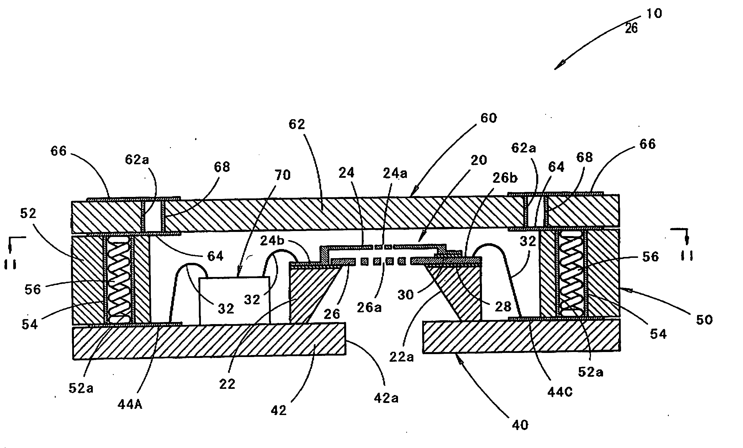
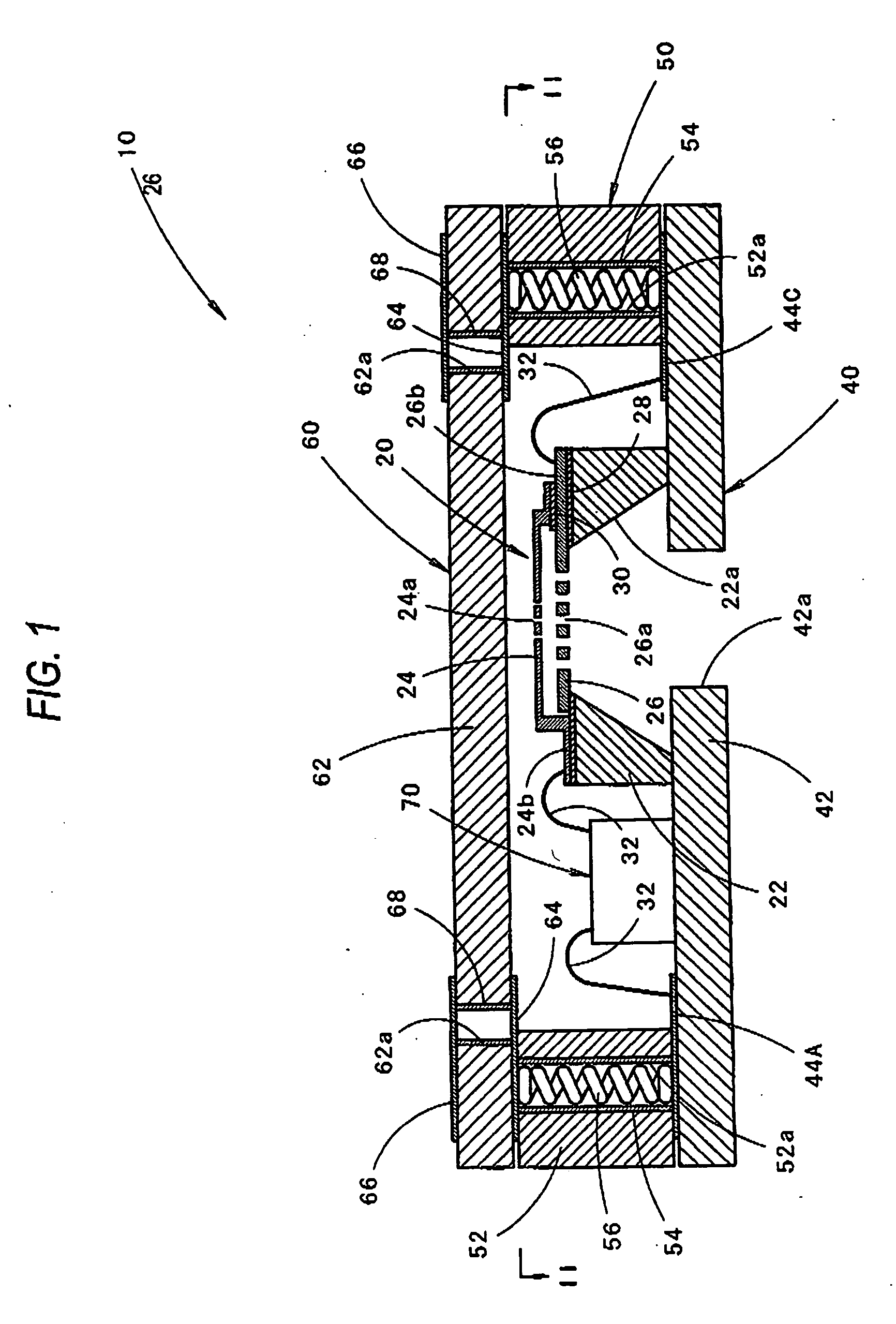
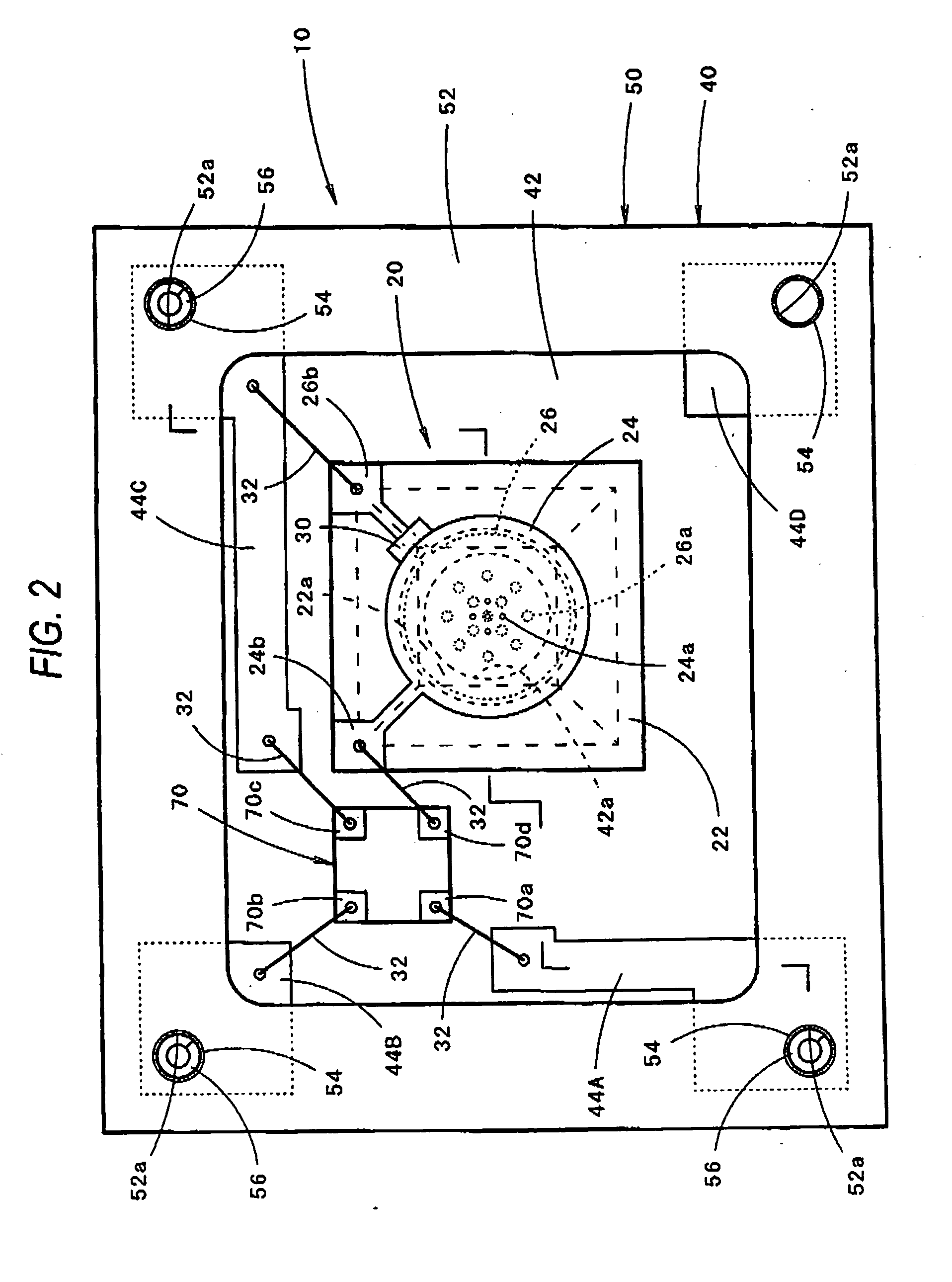
[0030]FIG. 1 is a sectional side view showing a state in which a condenser microphone 10 according to an embodiment of the invention is directed upward, and FIG. 2 is a view seen in a II-II line in FIG. 1. FIG. 1 is a sectional view taken along a I-I line in FIG. 2.

[0031] As shown in these drawings, the condenser microphone 10 according to the embodiment comprises a microphone element 20, a base board 40, a side board 50, a cover board 60 and an IC chip 70.

[0032] The microphone element 20 has such a structure that a diaphragm 24 and a fixed electrode 26 are disposed opposite to each other on a silicon board 22 having a central opening portion 22a formed therein, and is manufactured by using an MEMS technique.

[0033] The silicon board 22 is configured by single crystal silicon cut out to have a size of approximately 1 mm square from a silicon wafer and has a thickness of approximately 0.3...


PUM


Abstract

A microphone element having a diaphragm and a fixed electrode disposed opposite to each other on a silicon board having a central opening portion is mounted and fixed onto a base board having a sound hole. A perimeter-shaped side board and a cover board are mounted and fixed onto the board, thereby forming a back cavity on an upper side of the microphone element. The diaphragm and the fixed electrode are conducted to conductive layers of the cover board through conductive layers of the base board, and a conductive layer and a coiled spring in the side board respectively, and mounting on a surface of a printed board of an external apparatus can be carried out in a conductive layer on an upper surface thereof.

Description

BACKGROUND OF THE INVENTION [0001] 1. Field of the Invention [0002] The present invention relates to a condenser microphone and more particularly to a condenser microphone having a microphone element configured by using a silicon board. [0003] 2. Description of the Related Art [0004] In general, a condenser microphone has such a structure as to have a condenser constituting portion in which a diaphragm and a fixed electrode are disposed opposite to each other. In recent years, there has also been a devisal for manufacturing the condenser constituting portion as a microphone element by utilizing a so-called MEMS (Micro Electro Mechanical Systems) technique in order to reduce a size. [0005] For example, JP-A-2005-183437 discloses a condenser microphone including a microphone element in which a diaphragm and a fixed electrode are disposed opposite to each other over a silicon board having a central opening portion formed therein. In the condenser microphone, the microphone element is m...

Claims


Application Information

Patent Timeline
Patent Type & Authority Applications(United States)
IPC IPC(8): H04R25/00
CPCH04R19/04H01L2224/48091H01L2224/48137H01L2224/48227H01L2924/10253H01L2924/00014H01L2924/00
Inventor SAWAMOTO, NORIHIROFUJINAMI, HIROSHITSUKUDA, YASUNORIITO, MOTOAKIYONEHARA, KENTARO
Owner STAR MICRONICS
Why Eureka
Try Eureka