Control valve filter device

A filter device and control valve technology, applied in the direction of valve device, filter separation, membrane filter, etc., can solve problems affecting normal operation and achieve the effect of large effective area

Active Publication Date: 2012-07-11
PIOLAX CO LTD
View PDF6 Cites 4 Cited by
  • Summary
  • Abstract
  • Description
  • Claims
  • Application Information

AI Technical Summary

Problems solved by technology

If impurities or foreign matter contained in the fluid invade this control valve, it will affect its normal operation

Method used


Image

  • Control valve filter device
  • Control valve filter device
  • Control valve filter device

Examples


Embodiment Construction

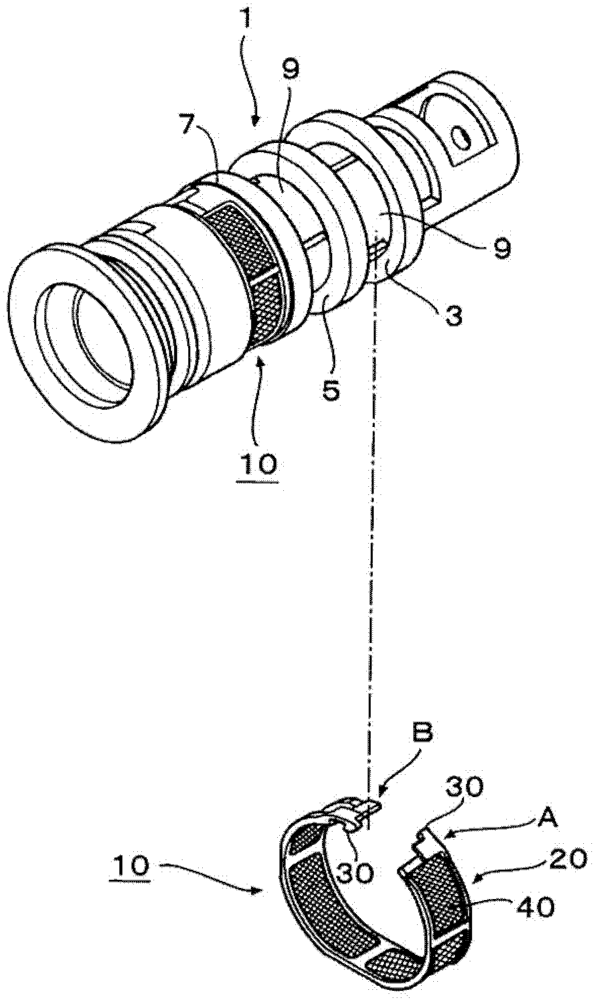
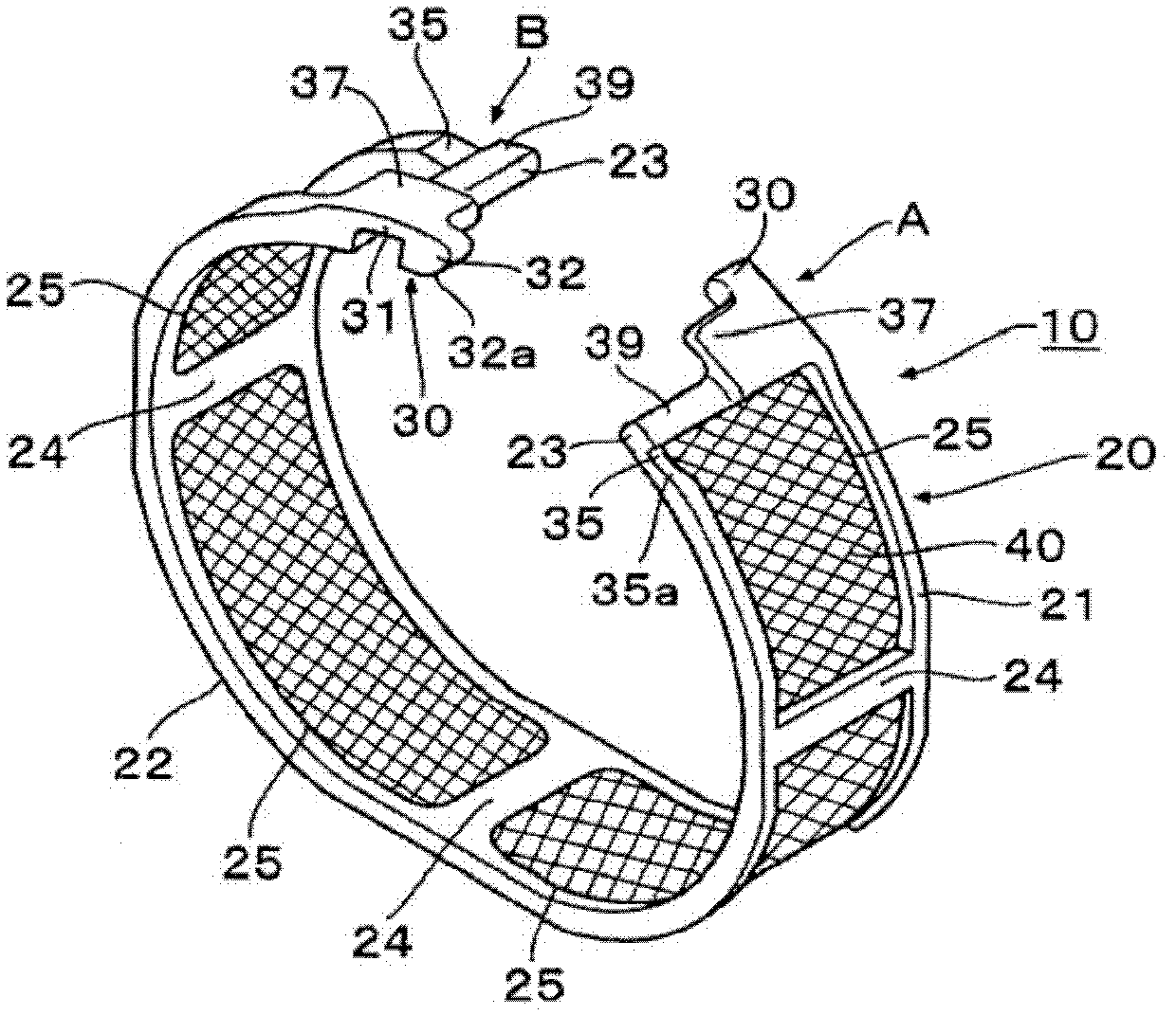
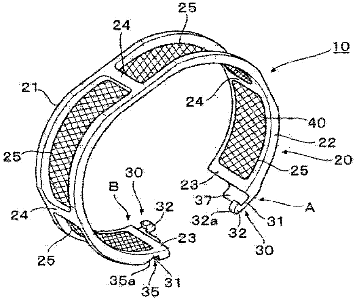
[0018] refer to Figures 1 to 5A and Figure 5B , describing an embodiment of a control valve filtering device.

[0019] For example, the control valve 1 is set in the oil pressure circuit of the motor vehicle engine to change the oil passage or perform pressure regulation, or it is set in the fuel supply system to perform fuel injection quantity adjustment, fuel injection timing adjustment, etc. Such as figure 1 As shown, a control valve filter device (filter device) 10 according to the present embodiment is mounted on a control valve 1 . On the outer periphery of the control valve 1, a plurality of circumferential grooves 3, 5 and 7 are formed at given intervals in the axial direction thereof. In the present embodiment, the filter device 10 is mounted to each of the circumferential groove 3 and the circumferential groove 7 located axially on both sides of the circumferential groove 5 . The circumferential grooves 3 , 5 and 7 are each provided with a port portion 9 commun...


PUM


Abstract

One embodiment provides a control valve filter device, including: a belt-like frame body curved into a ring shape so that its ends face each other, the frame body having an opening; a filter member provided in the opening of the frame body; an engagement claw extended from one of each of both corresponding lateral portions of the faced ends of the frame body; and a concave portion provided at the other of each of the both corresponding lateral portions of the faced ends of the frame body, so as to be engaged by the engagement claw, each concave portion being formed laterally of the opening of the frame body.

Description

technical field [0001] The present invention relates to a control valve filtering device, which is installed in a control valve controlling fluid pressure to prevent foreign matter from entering the control valve. Background technique [0002] In engines, for example, automatic transmissions of motor vehicles and the like, control valves are used in many cases for controlling the pressure of fluids such as fuel or oil, or for changing the passage of fuel or oil. If impurities or foreign matter contained in the fluid invade this control valve, it will affect its normal operation. Therefore, a filter is installed on this control valve to intercept the impurities contained in the fluid. [0003] JP-2002-285966-A discloses a filter in which a frame body (53, numbers in parentheses correspond to reference numerals in JP-2002-285966-A) is detachable at its end. At an end portion of the frame body (53), an engaging portion (55) for engaging both end portions and a holding portion...

Claims


Application Information

Patent Timeline
Patent Type & Authority Applications(China)
IPC IPC(8): F16K51/00B01D35/02B01D29/31
CPCB01D29/112B01D2201/4084
Inventor 木村岳
Owner PIOLAX CO LTD
Why Eureka
Try Eureka