Shutter device for camera

a shutter device and camera technology, applied in the field of shutter devices, can solve the problems of deteriorating the portability of the digital device, increasing the whole size of the lens unit, and increasing the size of the shutter device, so as to maintain the shutter device in a compact size

Inactive Publication Date: 2011-02-17
SUNG WOO ELECTRONICS CO LTD
View PDF8 Cites 8 Cited by
  • Summary
  • Abstract
  • Description
  • Claims
  • Application Information

AI Technical Summary

Benefits of technology

[0013]According to the present invention, a shutter device for camera operates a first shutter and a second shutter at high speed through a micro mini driver and a driving arm so that a camera module employed in a

Problems solved by technology

Therefore, there is a problem that the whole size of a lens unit, as well as the size of the shutter device, increases.
This problem eventua

Method used


Image

  • Shutter device for camera
  • Shutter device for camera
  • Shutter device for camera

Examples


Embodiment Construction

[0027]Hereinafter, a shutter device for a camera according to a first exemplary embodiment of the present invention will be described with reference to accompanying drawings.

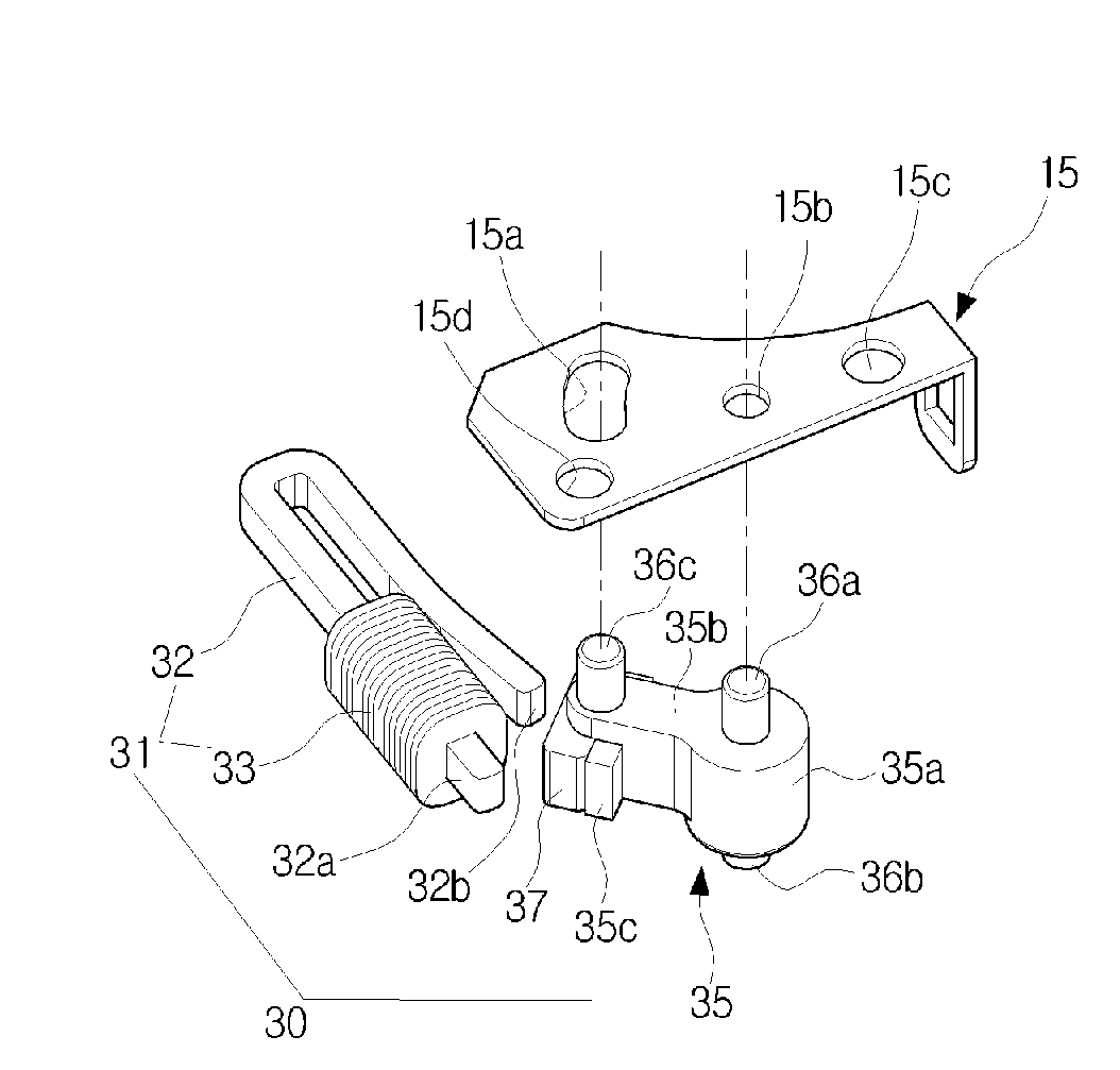
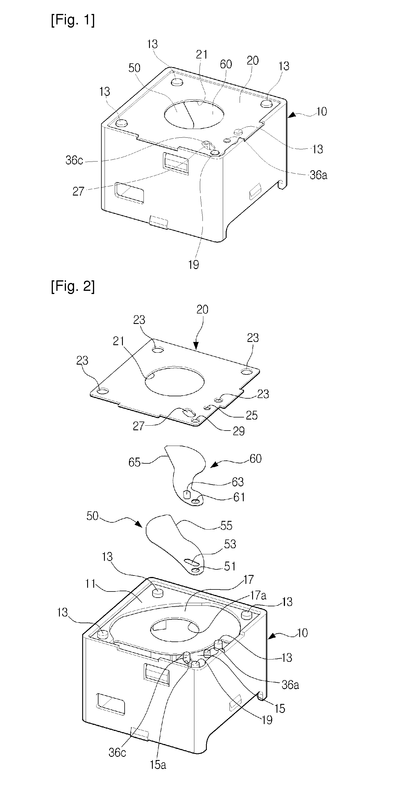
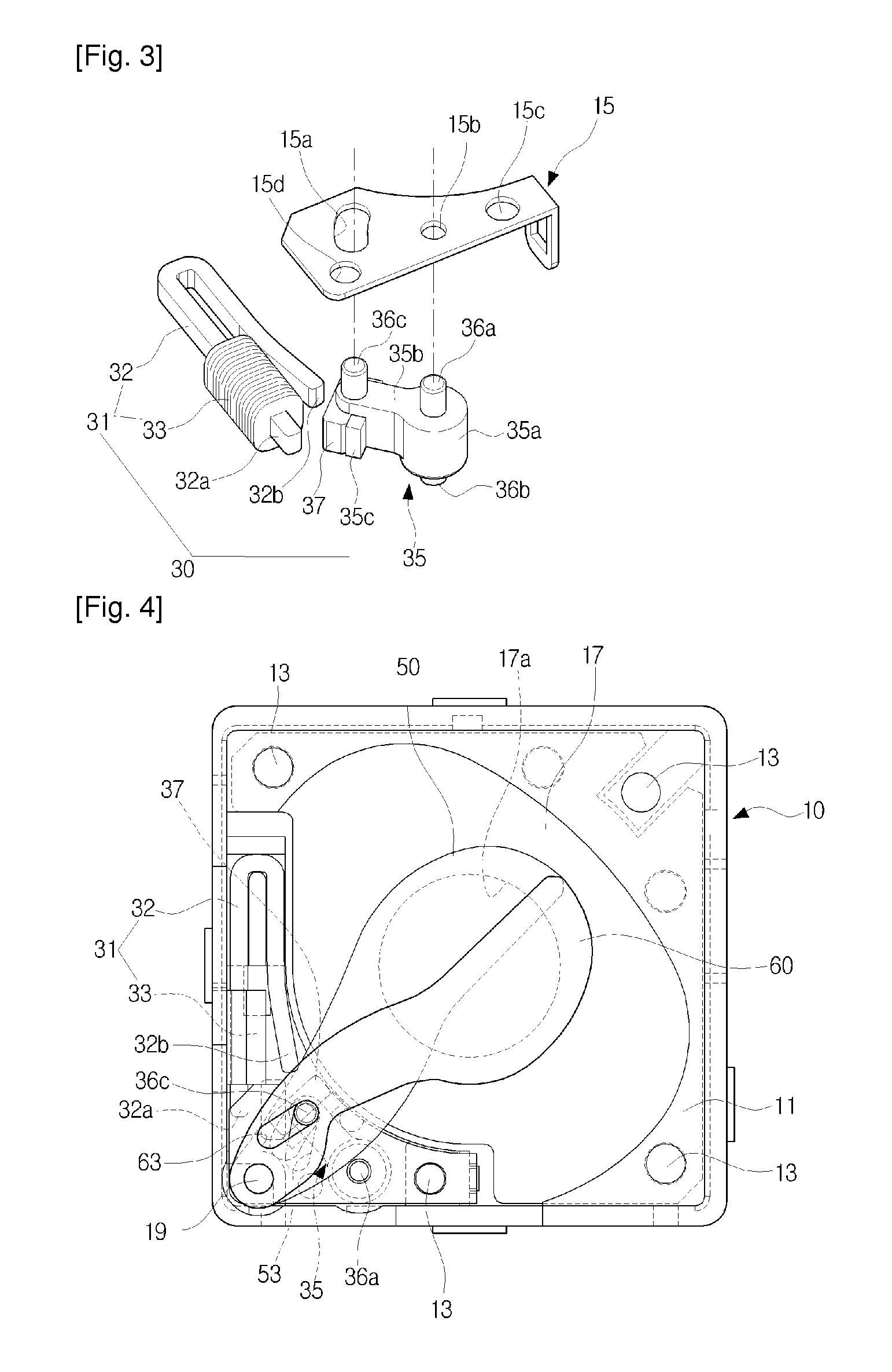
[0028]Referring to FIGS. 1 to 3, the shutter device according to the first exemplary embodiment of the present invention comprises a base 10, a driving part 30, and a first shutter and a second shutter 50, 60.

[0029]The base 10 is formed in a substantially rectangular parallelepiped shape to allow a lens module (not shown) to be seated therein, and has an extension part 11 formed on the upper portion of the base 10 along three inner corners. The extension part 11 is provided with a plurality of fixing protrusions 13 to fix a cover 20. Also, a fixing bracket 15 is disposed on the remaining corner of the base 10 to fix the driving part 30. Moreover, a predetermined circuit such as a printed circuit board (PCB) (not shown) is disposed inside the base 10 to apply current to a coil 33 of the driving part 30.

[0030]The ...


PUM


Abstract

The present invention relates to a shutter device for camera used for small-sized digital equipment and includes a base forming a light transmission hole to expose a film or charge-coupled device (CCD) to laser beam; an electromagnet mounted on one side of the base; a driving arm which is mounted on one side of the electromagnet on the base so as to pivot on the base; a first shutter and a second shutter to open and close the light transmission hole, which pivots on the part of the base in association with the pivoting of the driving arm; and a magnetic which is installed on the driving arm and has the north magnetic pole and the south magnetic pole at opposite ends of the magnetic or on surfaces opposite to the electromagnet. The driving arm drives the first shutter and the second shutter by pivoting in a clockwise or counter-clockwise direction by the attractive force and repulsive force generated between the electromagnet and the magnetic according to the direction of the electric current applied to the electromagnet, the electromagnet includes a bobbin and a coil wound around the bobbin, and each side of the bobbin having opposite poles of magnetic field is disposed adjacent to the north and south pole.

Description

TECHNICAL FIELD[0001]The present invention relates to a shutter device, and more particularly, to a shutter device for a camera used for a small-sized digital equipment.BACKGROUND ART[0002]With the development of digital technology, portable digital equipments such as a mobile communication terminal, a portable game console, a personal digital assistant (PDA), a personal multimedia player (PMP), and a digital camcorder are being launched as a product combining a camera function.[0003]A camera unit installed in such a portable small-sized digital equipment includes a shutter device to control the amount of light to obtain a necessary exposure like a general camera. In particular, if the camera is embedded in a mobile communication terminal, for example, in a mobile phone, it is essential to employ a mechanical shutter to photograph with high quality. It is also important to simplify the structure of the shutter device since a slim mobile phone requires a small-sized and slim camera m...

Claims


Application Information

Patent Timeline
IPC IPC(8): G03B9/08H04N5/235
CPCG03B9/08
Inventor LIM, DAE-SOONKIM, KYUNG-HOAHN, JIN-CHULKIM, TAE-JINJUNG, HO-YOUNG
Owner SUNG WOO ELECTRONICS CO LTD
Why Eureka
Try Eureka