
Intermediate transfer belt, production method thereof, and image-forming device using the intermediate transfer belt

a transfer belt and intermediate technology, applied in the direction of electrographic process, electrographic process apparatus, instruments, etc., can solve the problems of shortening the pot life of the solution (film forming solution) drastically, generating gel, and not being easy to remov

Inactive Publication Date: 2007-02-01
FUJIFILM BUSINESS INNOVATION CORP
View PDF6 Cites 56 Cited by
  • Summary
  • Abstract
  • Description
  • Claims
  • Application Information

AI Technical Summary

Benefits of technology

The present invention provides an intermediate transfer belt with a polyimide resin containing polyaniline particles with a maximum length of 10.0 μm or less. The image-forming device using this intermediate transfer belt can produce high-quality images with reduced image blurring and improved image quality. The method of producing the intermediate transfer belt involves pulverizing polyaniline particles, adding a dopant to make them conductive, blending with polyamic acid, and drying and sintering the mixture. The technical effects of this invention include improved image quality, reduced image blurring, and improved image forming device performance.

Problems solved by technology

Since undoped polyaniline is not highly soluble in the NMP or DMAc solvent, it often gelates therein, and easily generates gel when mixed with polyamic acid due to the influence of the acid, shortening the pot life of the solution (film forming solution) drastically.
In addition, the gel generated, which is soft in the solution, is not easily removed by filtration, and thus, the belt or sheet after casting often contains microgels of about 1.0 μm and larger gels of about several to 50 μm (occasionally, larger gels when the polyaniline is not dissolved sufficiently).
Further, the gels in the belt or sheet obtained after baking are harder, causing problems such as raised spots and irregularity on the surface of the belt or sheet and deterioration of the surface smoothness thereof.
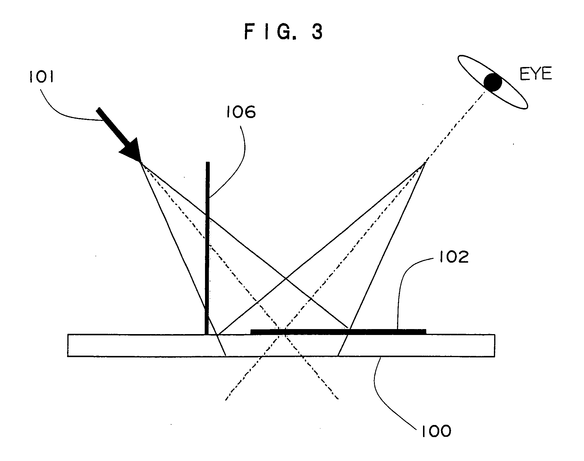
As a result, when applied to an intermediate transfer belt, the semiconductive belt or sheet thus obtained has problems such as inferior surface smoothness and fluctuation of resistivity in microregions caused by bulky polyaniline particles (bulky gels) present therein, consequently leading to problems in the quality of transferred image such as white deletion.

Method used


Image

  • Intermediate transfer belt, production method thereof, and image-forming device using the intermediate transfer belt
  • Intermediate transfer belt, production method thereof, and image-forming device using the intermediate transfer belt
  • Intermediate transfer belt, production method thereof, and image-forming device using the intermediate transfer belt

Examples


example 1

[0207] 3,3′,4,4′-biphenyltetracarboxylic dianhydride (BPDA) and pyromellitic dianhydride (PMDA) is added to a DMAc solution of 4,4′-diaminodiphenylether (ODA), and the mixture is stirred sufficiently under nitrogen atmosphere. The molar ratio of ODA:BPDA:PMDA is 1.00:0.55:0.45, and thus, a polyamic acid solution (A-1) at a concentration of 20 mass % is obtained.

[0208] Panipol PA manufactured by Panipol is made available as undoped polyaniline.

[0209] Separately, para-phenolsulfonic acid in an amount of 30% by mole equivalence of the undoped polyaniline (in other words, 60% mole equivalences with respect to 100% of half of the undoped polyaniline) is made available as dopant. The para-phenolsulfonic acid is added to and stirred in DMAc solvent under nitrogen atmosphere, to give a homogenous dopant solution at a concentration of 5 mass %.

[0210] An undoped polyaniline, Panipol PA manufacture by Panipol, is pulverized in a dry jet mill. The dry jet mill used is a counter jet mill (typ...

example 2

[0219] An intermediate transfer belt of Example 2 is prepared in a similar manner to Example 1, except that the polyaniline dispersion (B-1) used in Example 1 is replaced with the following polyaniline dispersion (B-2).

[0220] Part of the polyaniline particles collected in the product-collecting unit-1 (Φ100 cyclone) in the pulverized polyaniline obtained during preparation of the polyaniline dispersion (B-1) is collected as the second polyaniline particles; and a small portion thereof is dispersed in ethanol. Analysis of the particle size distribution of the second polyaniline particles shows that the 50 percentile particle diameter (volume basis) is 2.7 μm; the 90 percentile particle diameter, 4.3 μm, and the 100 percentile particle diameter (volume basis), 7.7 μm.

[0221] Then, 250 parts by mass of the pulverized second polyaniline particles and 25 parts by mass of PVP (polyvinylpyrrolidone) are added gradually under nitrogen atmosphere to the dopant solution at a concentration of...

example 3

[0288] A conductive coating agent aquaPASS-01 (aqueous solution of polyaniline sulfonic acid) manufactured by Mitsubishi Rayon Co., Ltd. is dried and pulverized, for example, in an evaporator, to give a powdery polyaniline sulfonic acid (PAS; average molecular weight: 10,000, average diameter: approximately 9 μm) as self-doping polyaniline.

[0289] The self-doping polyaniline, powdery polyaniline sulfonic acid, is pulverized in a dry jet mill. The dry jet mill used is a counter jet mill (type 100AFG) manufactured by Hosokawamicron Corporation.

[0290] The counter jet mill contains (1) a raw material-supplying unit FTS-20, (2) a counter jet mill 100AFG, (3) a product-collecting unit-1 (Φ100 cyclone), (4) a product-collecting unit-2 (P-bag: filtration area: 2.3 square meter), and (5) an exhaust blower. The main conditions for pulverization are as follows: pulverization air flow: 100 cubic meters per minute, air pressure: 600 kPa, and classification rotational velocity: 20,000 rpm.

[0291...


PUM


Abstract

The present invention provides an intermediate transfer belt comprising a polyimide resin comprising polyaniline, wherein the absolute maximum length of the largest particle of the polyaniline is approximately 10.0 μm or less, a preparation thereof, and an image-forming device comprising the intermediate transfer belt.

Description

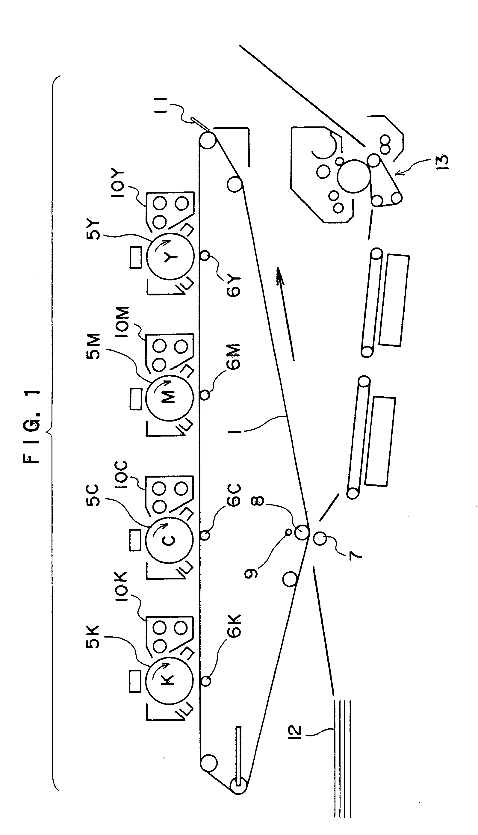
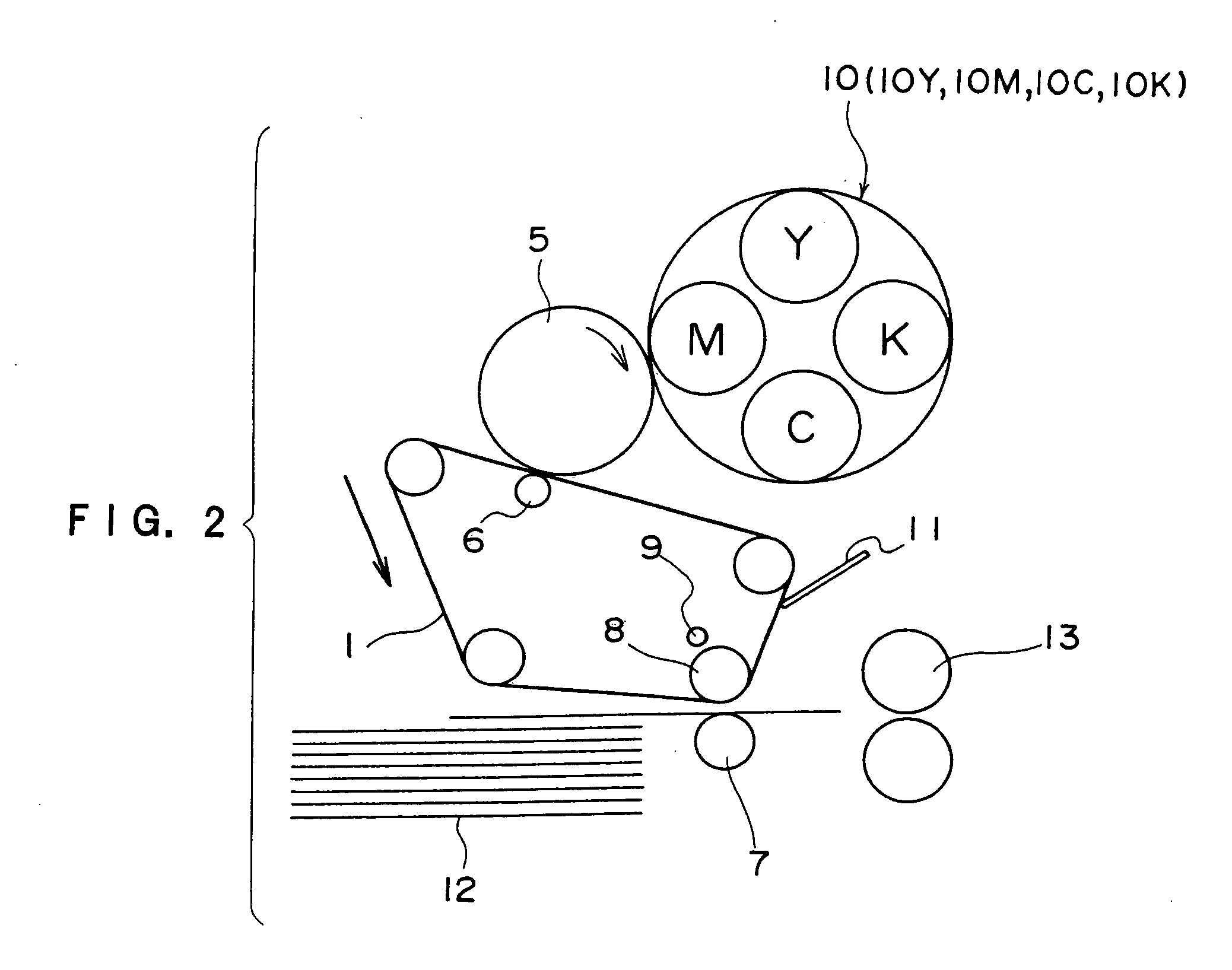
CROSS-REFERENCE TO RELATED APPLICATION [0001] This application claims priority under 35 USC 119 from Japanese Patent Application Nos. 2005-216336 and 2005-373614, the disclosures of which are incorporated by reference herein. BACKGROUND OF THE INVENTION [0002] 1. Field of the Invention [0003] The present invention relates to an image-forming device using an electrophotographic process, such as electrophotographic copying machine, laser printer, facsimile, and multi-function OA devices thereof. In particular to an intermediate transfer belt for use in image-forming devices that form an image by primary-transferring a toner image formed on an image holding member onto an intermediate transfer body and then retransferring the image onto a recording medium such as paper, a method of producing the same, and an image-forming device equipped with the intermediate transfer belt. [0004] 2. Description of the Related Art [0005] In image-forming devices using the electrophotographic processes,...

Claims


Application Information

Patent Timeline
Patent Type & Authority Applications(United States)
IPC IPC(8): G03G15/00
CPCC08L79/02C08L79/08C08L2205/02G03G15/1605C08L2666/20G03G15/162
Inventor KATOH, SEIICHIMIYAMOTO, HIROSHIMIYAMOTO, TSUYOSHIMORITA, SHOICHIFURUYA, TOSHIE
Owner FUJIFILM BUSINESS INNOVATION CORP
Learn More