Robot cleaner

a robot cleaner and cleaner technology, applied in the field of robot cleaners, can solve the problems of reducing flow resistance and length, and achieve the effect of increasing suction pressur

Active Publication Date: 2011-05-05
LG ELECTRONICS INC
View PDF7 Cites 20 Cited by
  • Summary
  • Abstract
  • Description
  • Claims
  • Application Information

AI Technical Summary

Benefits of technology

[0031]In the above configurations, a suction pressure may be increased without increasing a battery or a capacity of the driving motor which drives the suction fan.

Problems solved by technology

This may reduce a length of the suction channel from the suction port to the dust box, and thus reduce a flow resistance.

Method used


Image

  • Robot cleaner
  • Robot cleaner
  • Robot cleaner

Examples


Embodiment Construction

[0051]Description will now be given in detail of the present invention, with reference to the accompanying drawings.

[0052]For the sake of brief description with reference to the drawings, the same or equivalent components will be provided with the same reference numbers, and description thereof will not be repeated.

[0053]Hereinafter, preferred embodiments of the present invention will be explained in more detail with reference to the attached drawings. Detailed explanations about similar configurations to the conventional configurations will be omitted.

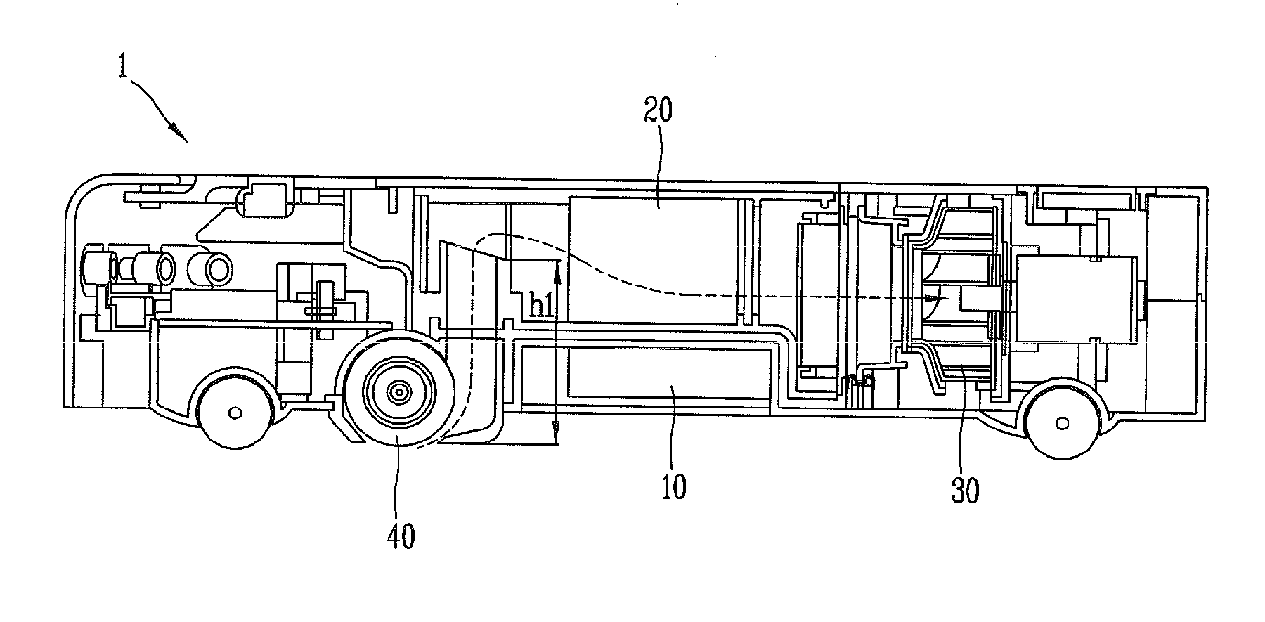
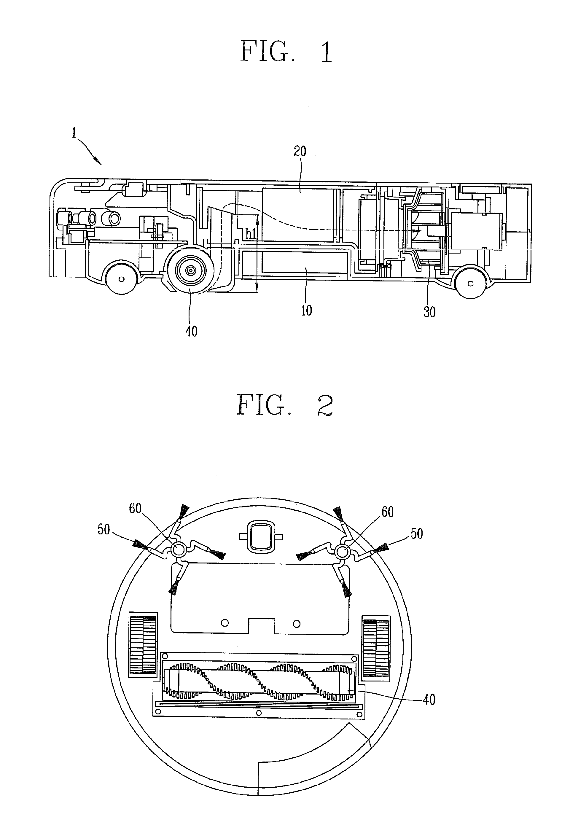
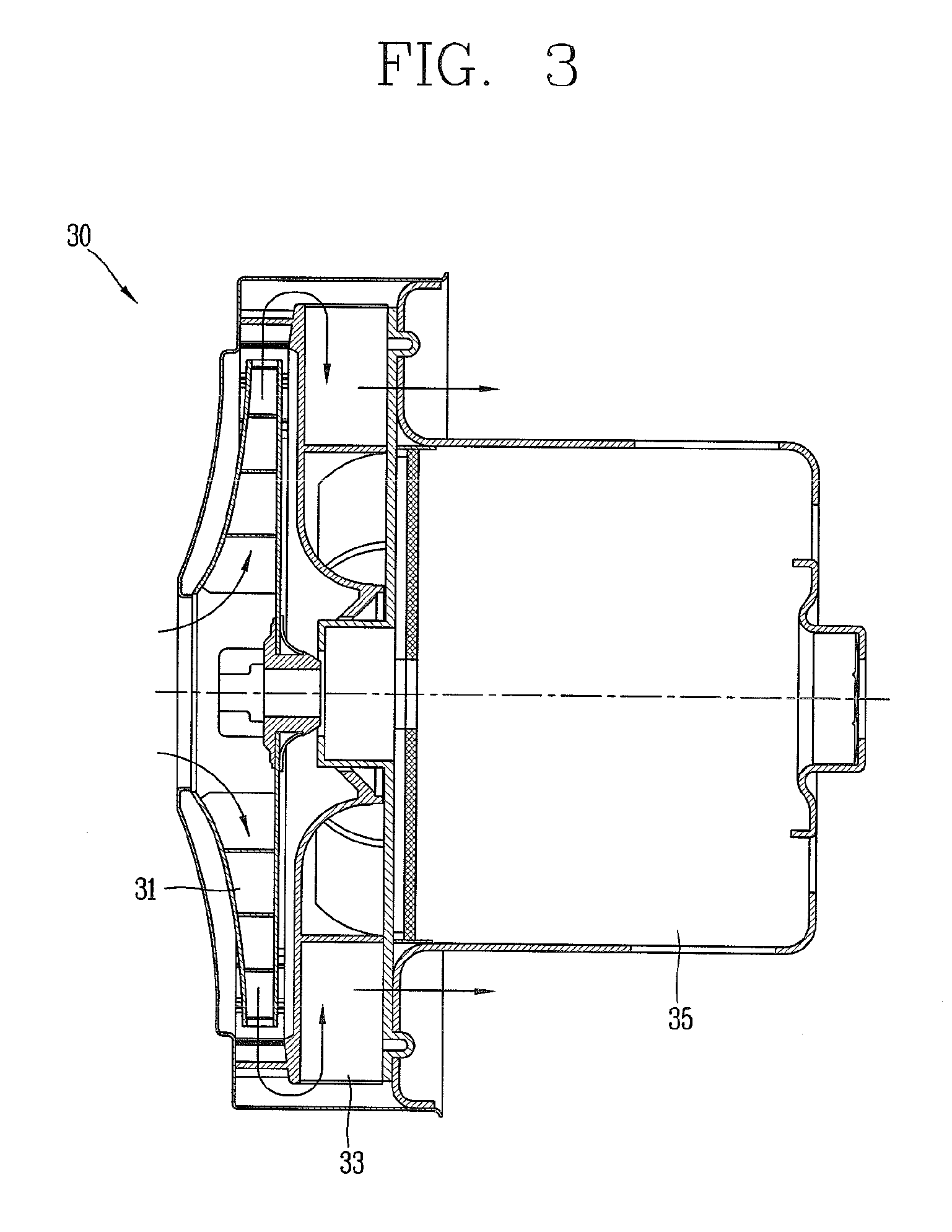
[0054]FIG. 5 is a side sectional view of a robot cleaner according to one embodiment of the present invention, FIG. 6 is a planar view showing inside of the robot cleaner of FIG. 5, and FIG. 7 is an enlargement view showing inside of a part ‘W’ of FIG. 6.

[0055]First of all, directions disclosed in the specification will be defined. When wheels of both sides of the robot cleaner are simultaneously rotated, a direction to which the robo...


PUM


Abstract

A robot cleaner comprises a main body having a suction port at a bottom surface thereof, a pair of wheel assemblies disposed at both sides of the main body, and configured to move the main body, a dust box mounted to contact the bottom surface of the main body, and configured to collect dust sucked through the suction port, a filter unit configured to filter air discharged from the dust box, a suction fan configured to form a suction pressure on a suction channel defined by the suction port, the dust box and the filter unit, and a battery disposed at a side of the dust box.

Description

CROSS-REFERENCE TO A RELATED APPLICATION[0001]Pursuant to 35 U.S.C. §119(a), this application claims the benefit of earlier filing date and right of priority to Korean Application No. 10-2009-0105147 filed on Nov. 2, 2009, 10-2009-0110434 filed on Nov. 16, 2009 and 10-2009-0111120 filed on Nov. 17, 2009, the content of which is incorporated by reference herein in its entirety.BACKGROUND OF THE INVENTION[0002]1. Field of the Invention[0003]The present invention relates to a robot cleaner.[0004]2. Background of the Invention[0005]A cleaner is an apparatus configured to clean an indoor room by removing foreign materials. As the cleaner, generally used is a vacuum cleaner configured to suck foreign materials by using a suction force of a low pressure part. Recently, is being developed a robot cleaner capable of removing foreign materials from an indoor floor with autonomously moving through an automatic running function.[0006]The robot cleaner includes a distance sensor configured to se...

Claims


Application Information

Patent Timeline
Patent Type & Authority Applications(United States)
IPC IPC(8): A47L9/10
CPCA47L5/22A47L9/0427A47L2201/00A47L9/2884A47L9/122
Inventor KIM, BONGJUKIM, SANGYUNPARK, JONGILCHOI, WOOJINSHIN, DONGMYUNGREW, HOSEONKIM, SANGJOJUNG, YOUNGGYU
Owner LG ELECTRONICS INC
Why Eureka
Try Eureka