Eureka AIR delivers breakthrough ideas for toughest innovation challenges, trusted by R&D personnel around the world.

Method for operating a refrigerant circuit of a cooling system of a vehicle

A refrigerant circuit and refrigeration equipment technology, applied in heating/cooling equipment, refrigerators, refrigeration components, etc., can solve problems such as regulating supercooling, refrigerant escape, and high density of refrigerant

Active Publication Date: 2020-08-11
AUDI AG
View PDF28 Cites 0 Cited by
  • Summary
  • Abstract
  • Description
  • Claims
  • Application Information

AI Technical Summary

Problems solved by technology

The higher low pressure disadvantageously leads to a higher density of the refrigerant on the low pressure side and at the same time there is a risk of premature superheating of the refrigerant after the refrigerator and thus the escape of the refrigerant at the low pressure-refrigerant collector
If a refrigerant collector on the high pressure side is used, the effect that subcooling at the condenser or gas cooler can no longer be regulated since the refrigerant collector is no longer fully supplied with refrigerant

Method used


Image

  • Method for operating a refrigerant circuit of a cooling system of a vehicle
  • Method for operating a refrigerant circuit of a cooling system of a vehicle

Examples


Embodiment Construction

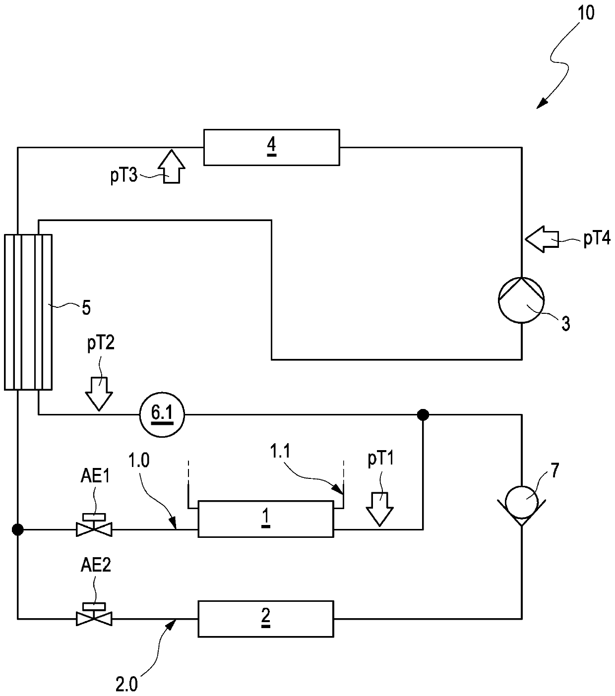
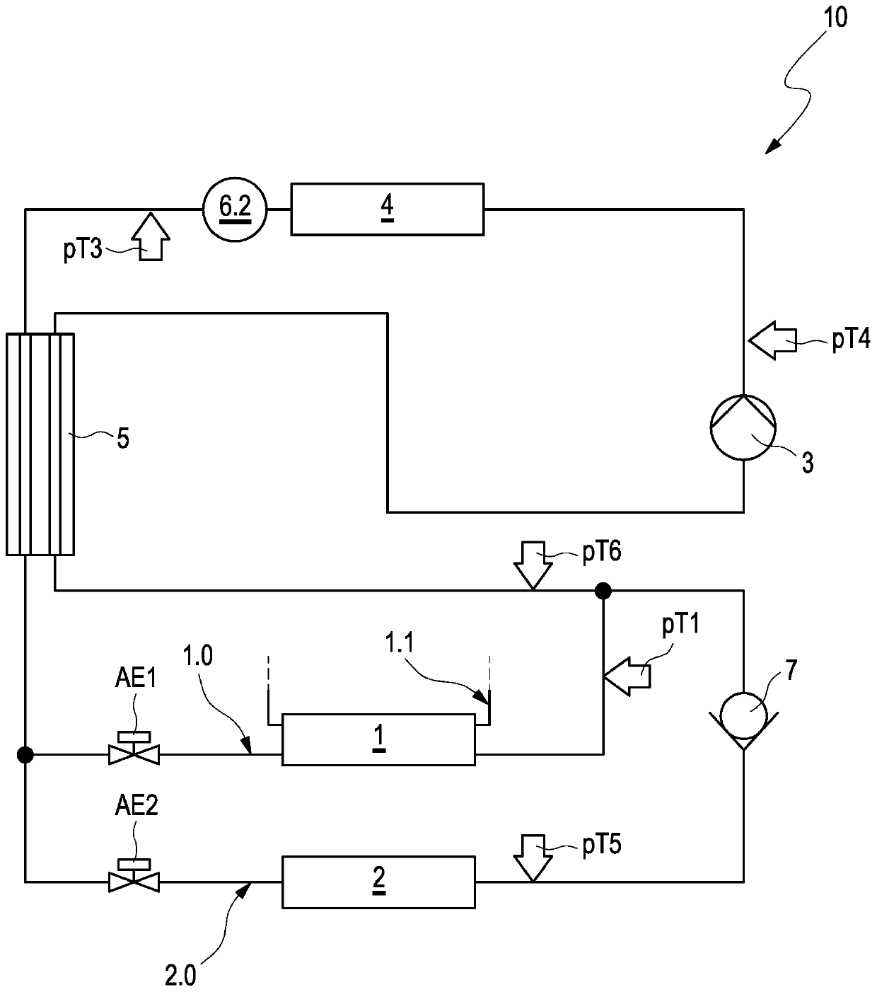
[0029] For simplicity, figure 1 with figure 2In each case, a refrigerant circuit 10 of a refrigeration system of a vehicle is shown, which refrigerant circuit is provided for pure AC operation (refrigeration system operation). Since the basic idea used to describe the method can be fully explained with a simple wiring concept and the functionality can be transferred directly to the heat pump-capable device and its inactive sectors, a functional expansion regarding the operation of the heat pump is omitted. The refrigerant circuits 10 are constructed with the same basic structure and differ in each case with regard to the arrangement of the refrigerant collectors as low-pressure or high-pressure refrigerant collectors. It should be mentioned here that the refrigerant collector arranged on the low-pressure side can be used for both subcritical and supercritical operating refrigeration equipment, while the high-pressure collector is mainly used for purely subcritical operating ...


PUM


Abstract

A method of operating a refrigerant circuit (10) of a cooling system of a vehicle in cooling system mode is disclosed, the refrigerant circuit having a chiller branch (1.0) which includes a chiller (1) and a first expansion element (AE1) connected upstream from it and being thermally coupled to a coolant circuit (1.1); at least one interior evaporator branch (2.0) connected in parallel with the chiller branch (1.0), comprising an interior evaporator (2), a second expansion element (AE2) connected upstream from it, and a segmentation element connected downstream from the interior evaporator (2), being adapted to prevent a backflow of refrigerant into the interior evaporator; a refrigerant compressor (3); and a condenser or gas cooler (4), wherein the cooling system mode is carried out in single chiller mode by closing the second expansion element (AE2) and aspirating the refrigerant from the interior evaporator by the starting or already started refrigerant compressor (3).

Description

technical field [0001] The invention relates to a method for operating a refrigerant circuit of a refrigeration system of a vehicle during refrigeration system operation. Background technique [0002] The use of refrigerant circuits in vehicle air conditioning systems is known, some variants of which provide for a 2-evaporator arrangement, namely a front evaporator and a rear evaporator. Depending on the connection and the active / active operation of the corresponding heat transfer, the requirement of the active refrigerant required in the refrigerant circuit will vary. [0003] In addition to the front evaporator, electrified vehicles also require a separate cooling device as at least one interior evaporator for temperature control and regulation of the energy store, which is usually realized in the form of a high-voltage battery. This type of cooling can be achieved through a refrigerant circuit and is called active battery cooling. Such a cooling device is realized as a ...

Claims


Application Information

Patent Timeline
IPC IPC(8): F25B41/04F25B41/06F25B5/02F25B41/20F25B41/325
CPCF25B5/02F25B41/22F25B41/31B60H1/00278B60H1/00392B60H1/00878B60H2001/00949B60H2001/00957B60H1/00007B60H2001/00928B60H1/00899B60H1/22B60H1/32281B60H1/00428F25B2400/19
Inventor D·施罗德H·罗腾科尔布
Owner AUDI AG
Why Eureka
Eureka Blog
Learn More