Hydraulic power steering system with charging valve and air cushion in the tank

a technology of charging valve and air cushion, which is applied in the direction of power driven steering, functional valve types, aeration devices, etc., can solve the problems of limiting the speed and capacity of the power steering pump, and the use of expensive injector designs

Inactive Publication Date: 2014-02-25
IXETIC BAD HOMBURG
View PDF38 Cites 0 Cited by
  • Summary
  • Abstract
  • Description
  • Claims
  • Application Information

AI Technical Summary

Benefits of technology

[0005]In accordance with an embodiment of the present invention, the present invention provides that the suction pressure of the pump may be improved when the low-pressure or suction area of a steering system is isolated from the atmosphere using a hermetic tank or a hermetically sealed suction area in conjunction with an auxiliary device which controls the pressure level required in the suction area. In steering systems commonly used today, the level of the pressure medium in the reservoir or tank constantly changes due to temperature changes during operation. An air vent may ensure that there is always a balancing pressure with respect to the environment, irrespective of the level in the reservoir. If the air vent is replaced with a self-priming pressure-limiting valve, the oil level changes, in conjunction with this valve, which can be used to selectively control the pressure inside the reservoir, and thus, the suction pressure of the pump. In this process, the liquid column in the tank functions as a piston pump.
[0015]Another preferred design provides a power steering system in which the suction pressure of the power steering pump may be increased by the bias of the air in the tank or suction area. Advantageously, this may allow avoidance of cavitation at high speeds and high delivery rates, which may eliminate the need for expensive injector designs.

Problems solved by technology

One problem with these systems is that cavitation occurs at the power steering pump because of insufficient suction pressure, which limits the speed and capacity of the power steering pump.
Alternatively, expensive injector designs must be used with such power steering pumps in order to achieve higher suction pressures.

Method used


Image

  • Hydraulic power steering system with charging valve and air cushion in the tank
  • Hydraulic power steering system with charging valve and air cushion in the tank

Examples


Embodiment Construction

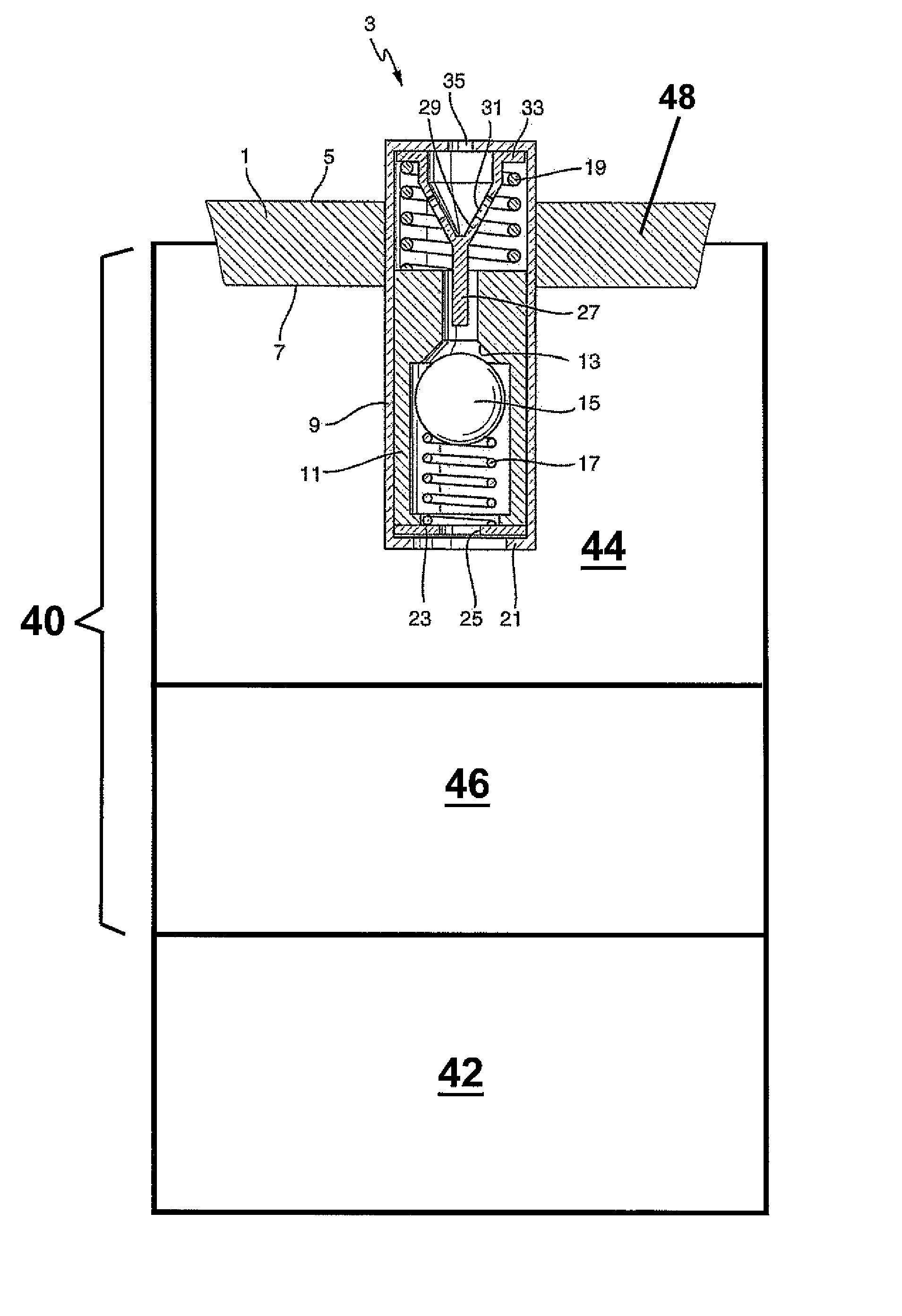
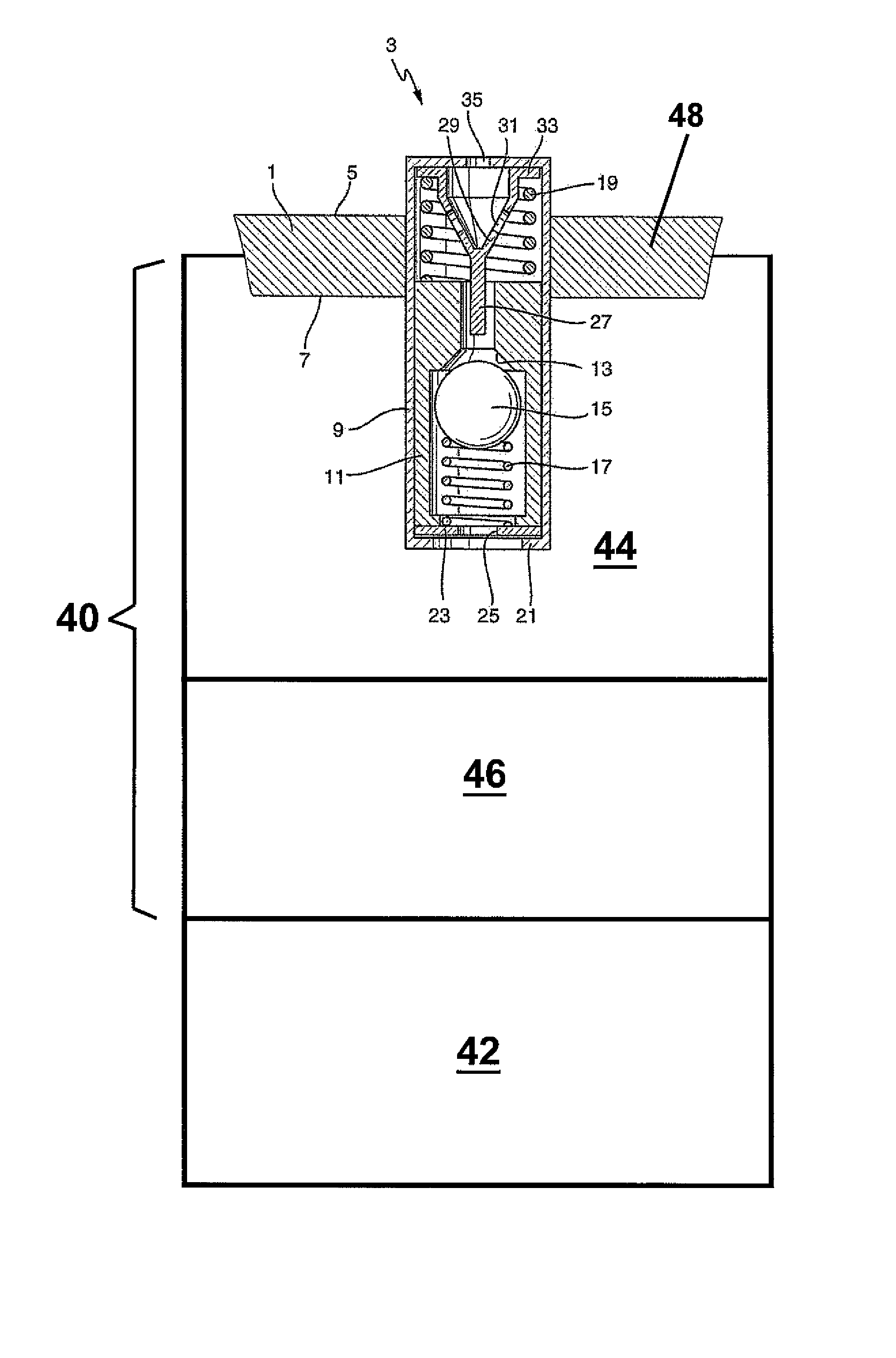
[0019]A valve device 3 according to the present invention is disposed in a wall 1 of an oil reservoir or tank 40 for a pump 42, the wall possibly forming part of a reservoir cap 48. Side 5 of the reservoir wall is at atmospheric pressure, while side 7 of reservoir wall 1 faces a suction area 44 of the power steering system, and therefore constitutes the inner side of the oil reservoir 40. The oil reservoir 40 itself and the suction area 44 of the power steering system are hermetically sealed off from the ambient pressure. Valve device 3 has a valve housing 9. A valve seat sleeve 11 is slidably supported in valve housing 9. Valve seat sleeve 11 includes a conical valve seat 13, which serves as a valve seat for a closure member 15 in the form of a ball. Ball 15 and valve seat 13 are shown in an open position to better illustrate the component parts. However, in reality, ball 15 would be pressed against valve seat 13 by a first, relatively weak spring 17. A second, significantly strong...


PUM


Abstract

A hydraulic power steering system which includes a tank and a power steering pump which takes in a pressure medium from an intake area which is decoupled from the prevailing atmospheric pressure on the side of the tank wall and delivers it under pressure to the power steering system. A valve device builds up a pre-pressure in the intake area and prevents a negative pressure and a positive pressure from building up on the interior of the oil tank.

Description

[0001]The present invention relates to a hydraulic power steering system having a tank and a power steering pump which draws in a pressure medium from a suction area and delivers it under pressure into the power steering system.BACKGROUND[0002]Power steering systems of this kind are generally known. One problem with these systems is that cavitation occurs at the power steering pump because of insufficient suction pressure, which limits the speed and capacity of the power steering pump. Alternatively, expensive injector designs must be used with such power steering pumps in order to achieve higher suction pressures.SUMMARY OF THE INVENTION[0003]An object of the present invention is to provide a hydraulic power steering system which will overcome these disadvantages.[0004]The present invention provides a hydraulic power steering system having a tank and a power steering pump which draws in a pressure medium from a suction area and delivers it under pressure into the power steering sys...

Claims


Application Information

Patent Timeline
Patent Type & Authority Patents(United States)
IPC IPC(8): F16K24/00F16K17/26F04B49/00
CPCF16K24/00B62D5/062F16K17/196F15B1/265Y10T137/7779Y10T137/7777Y10T137/7771
Inventor PARSCH, WILLI
Owner IXETIC BAD HOMBURG
Why Eureka
Try Eureka