Draining device

a technology of a draining device and a nozzle, which is applied in the direction of gas/liquid distribution and storage, pumping plants, jet propulsion plants, etc., can solve the problems of generating adverse pressure gradients, ice damage and additional unnecessary weight, and flammable fluid build-up within the flight envelope of aircraft, so as to improve the drainage capacity

Inactive Publication Date: 2013-12-12
SHORT BROTHERS
View PDF4 Cites 13 Cited by
  • Summary
  • Abstract
  • Description
  • Claims
  • Application Information

AI Technical Summary

Benefits of technology

[0006]It is an object of the invention to propose a draining device that overcomes the above mentioned drawback, and in particular enhance the drainage capacity when the aircraft is flying or taxiing on the ground.

Problems solved by technology

The build-up of any flammable fluid within the flight envelope of the aircraft represents a fire hazard.
The build-up of water within the flight envelope of the aircraft could result in potential issues including ice damage and additional unnecessary weight.
However, when the aircraft is flying on the ground with the engines operating, adverse pressure gradients located in a vicinity of the outlet of the drain may prevent the natural drainage from occurring.
Such adverse pressure gradients may be generated by the action of the airflow over the structure of the aircraft.
However, this is not satisfactory when an excessive adverse pressure gradient exists which might prevent effective drainage to occur.

Method used


Image

  • Draining device
  • Draining device
  • Draining device

Examples


Embodiment Construction

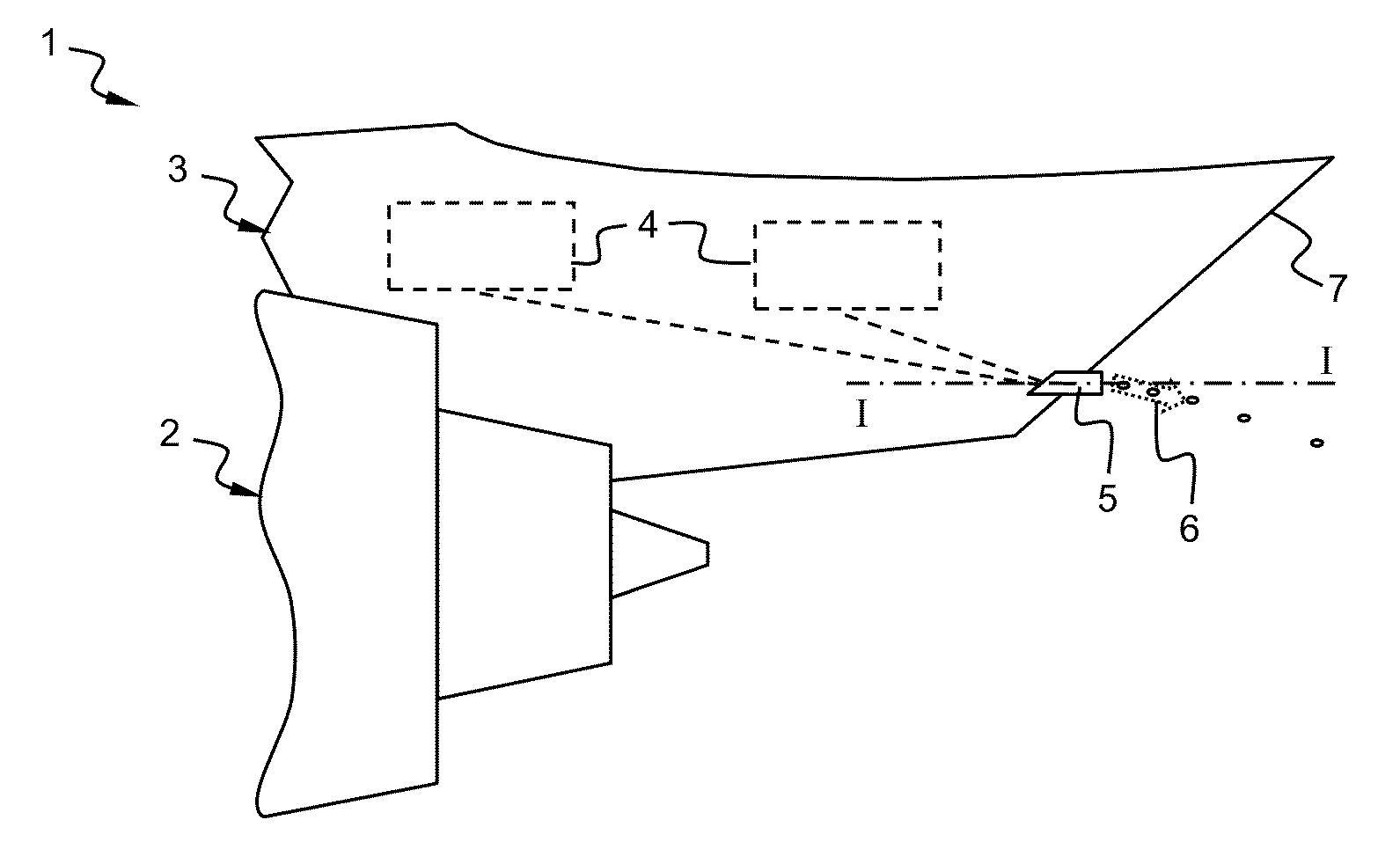
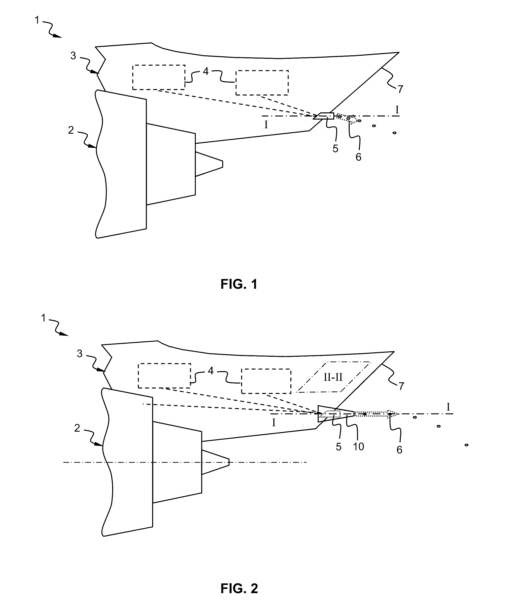
[0041]FIG. 2 is a side view partially illustrating an aircraft 1, in particular a rear part of an aircraft engine 2 and a rear part of an engine support strut 3 for supporting the aircraft engine. Fluids 6 may leak from various components and lines into various regions 4 of the engine support strut 3 (e.g. engine components and accessories, the gearbox, air-conditioning component, fuel lines, hydraulic lines, valves, the wing fuel tank, etc . . . ). These fluids 6 are drained away and discharged away from the aircraft by means of the drain tube 5. The drain tube 5 is fluidly connected to the various regions 4 of the engine support strut 3. According to an aspect of the invention, a draining device 10 comprising the drain tube 5 is arranged on the trailing edge 7 of the engine support strut 3. However, the draining device may also be adapted to drain unwanted fluid from other regions of the aircraft not limited to the engine support strut, for example from the aircraft engine 2 by fl...


PUM


Abstract

A draining device for draining a fluid from an aircraft engine support strut includes a suction arrangement having an inlet and extending along a longitudinal main axis to form a plenum chamber and a drain tube fluidly connected to the aircraft engine support strut and extending along the longitudinal main axis, the drain tube ending by an outlet, the outlet of the drain tube terminating within the plenum chamber of the suction arrangement. An air flow entering the inlet of the suction arrangement causes a low-pressure region to be created within the plenum chamber, substantially downstream the outlet of the drain tube.

Description

FIELD OF THE INVENTION[0001]The present invention relates to a draining device.[0002]Such a draining device would find a particular, though non exclusive, application, in association with an engine support strut, more particularly for installation on a pylon for supporting an engine of an aircraft used in the aerospace industry.BACKGROUND OF THE INVENTION[0003]FIG. 1 is a side view partially illustrating an aircraft 1, in particular a rear part of an aircraft engine 2 and of a structure or pylon 3 for supporting said aircraft engine. Various components and lines may leak fluids into separate regions 4 of an engine support strut. For example, said components may be engine components and accessories, the gearbox, air-conditioning component, fuel lines, hydraulic lines, valves, the wing fuel tank, etc . . . The leaking fluids may be for example oil, lubricant, hydraulic fluid, fuel, etc . . . Further, water may condense within said regions. The build-up of any flammable fluid within th...

Claims


Application Information

Patent Timeline
Patent Type & Authority Applications(United States)
IPC IPC(8): F02C7/20
CPCF02C7/20B64C1/1453F01D25/32Y10T137/0391Y10T137/86083
Inventor RICHARDSON, JOHN
Owner SHORT BROTHERS
Why Eureka
Try Eureka