Evaporator

a technology of evaporator and water tank, which is applied in the field of evaporators, can solve the problems of described evaporators and lack of water drainage performance, and achieve the effects of enhancing drainage performance, preventing a drop in the cooling performance of evaporators, and enhancing drainage performan

Inactive Publication Date: 2008-08-28
KEIHIN THERMAL TECH CORP
View PDF5 Cites 18 Cited by
  • Summary
  • Abstract
  • Description
  • Claims
  • Application Information

AI Technical Summary

Benefits of technology

[0026]In the evaporator of any one of pars. 1) to 3), a plurality of heat exchange tubes are arranged in rows spaced apart from each other in the front-rear direction and at predetermined intervals in the left-right direction, and fins are each disposed between and joined to the heat exchange tubes adjacent to each other in the left-right direction. With this evaporator, condensed water generated on the surface of the fins is attracted, by the capillary effect, toward connection portions between the heat exchange tubes and the fins; and the condensed water attracted to the connection portions between the rear heat exchange tubes and the fins is caused to flow frontward by the effect of air flowing through air-passing clearances each being formed between the heat exchange tubes adjacent to each other in the left-right direction and is attracted, by the capillary effect, toward the drainage acceleration members, thereby entering the drain channels each being formed between the heat exchange tube and the drainage acceleration member. In the case where a gap between the adjacent front and rear heat exchange tubes is rendered identical with that of the evaporator described in the above-described publication, the cross-sectional area of a drain channel formed between the front heat exchange tube and the drainage acceleration member and between the rear heat exchange tube and the drainage acceleration member becomes relatively small. Thus, by virtue of the capillary effect, the condensed water is drained downward through the drain channels without stagnation in the drain channels. Accordingly, the evaporator exhibits enhanced drainage performance. Further, enhanced drainage of condensed water enables suppression of freezing of condensed water in the drain channels, thereby preventing a drop in cooling performance of the evaporator.
[0027]With the evaporator of par. 4), the condensed water which is caused to flow to the drainage acceleration member by the effect of air flow and the capillary effect is drained downward along the drain groove of the drainage acceleration member. Thus, drainage performance is enhanced.
[0028]With the evaporator of par. 6), the condensed water which enters the drain channel in the form of the gap between the heat exchange tube and the drainage acceleration member is efficiently drained downward through the drain channel. Thus, performance on drainage of condensed water is enhanced.
[0029]With the evaporator of par. 7), the condensed water which enters the drain channel in the form of the recess formed between the heat exchange tube and the drainage acceleration member is efficiently drained downward through the drain channel.
[0030]With the evaporator of par. 13), the condensed water which enters the drain channel in the form of the gap between the heat exchange tube and the drainage acceleration member is efficiently drained downward through the drain channel. Thus, performance on drainage of condensed water is enhanced.
[0031]With the evaporator of par. 14), the condensed water which is caused to flow to the drainage acceleration member by the effect of air flow and the capillary effect is drained downward along the drain groove of the drainage acceleration member. Thus, drainage performance is enhanced.

Problems solved by technology

However, the evaporator described in the above-mentioned publication does not have a sufficient water drainage performance when the quantity of condensed water increases.

Method used


Image

  • Evaporator
  • Evaporator
  • Evaporator

Examples


embodiment 1

[0049]The present embodiment is illustrated in FIGS. 1 to 10.

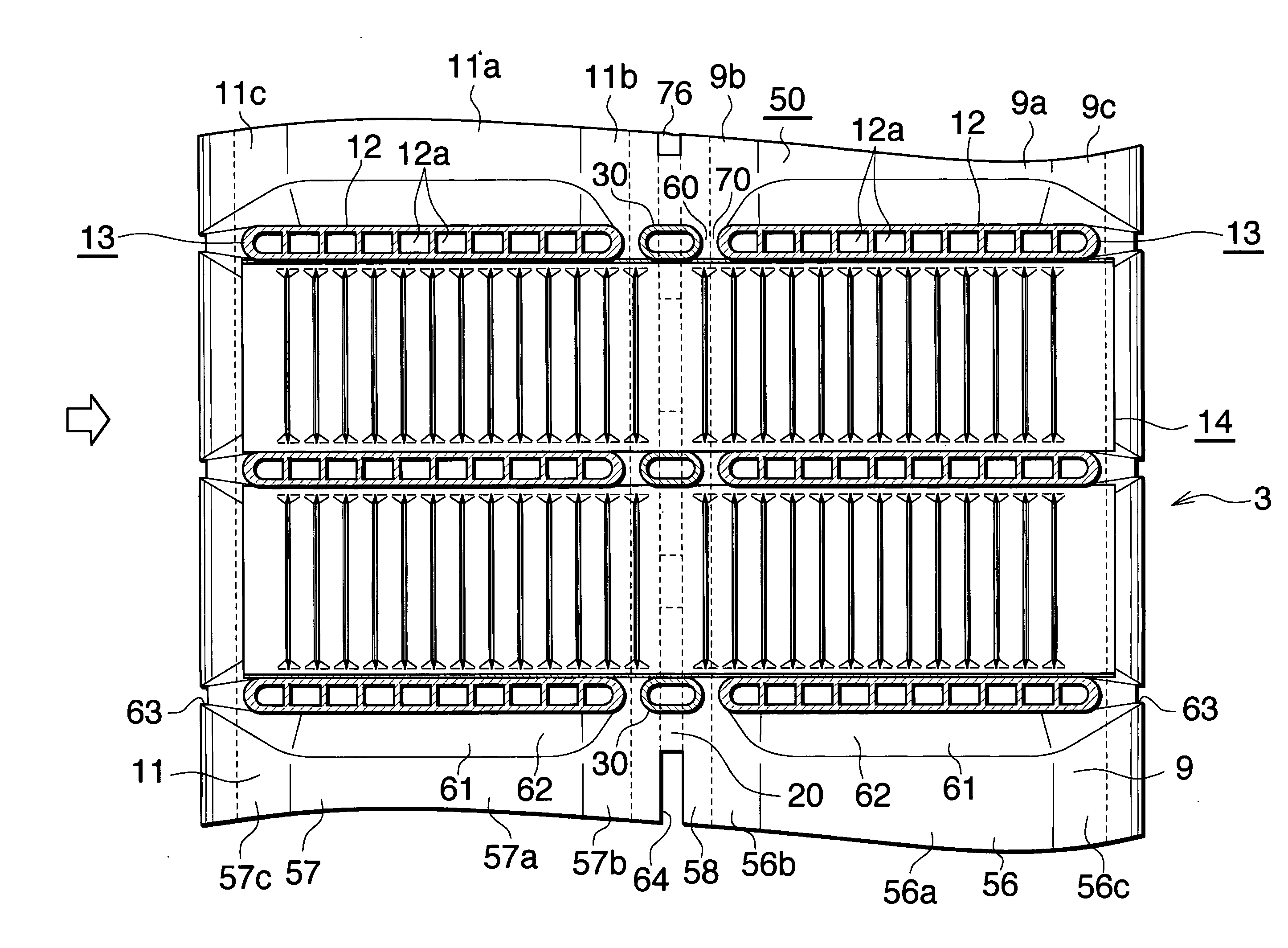
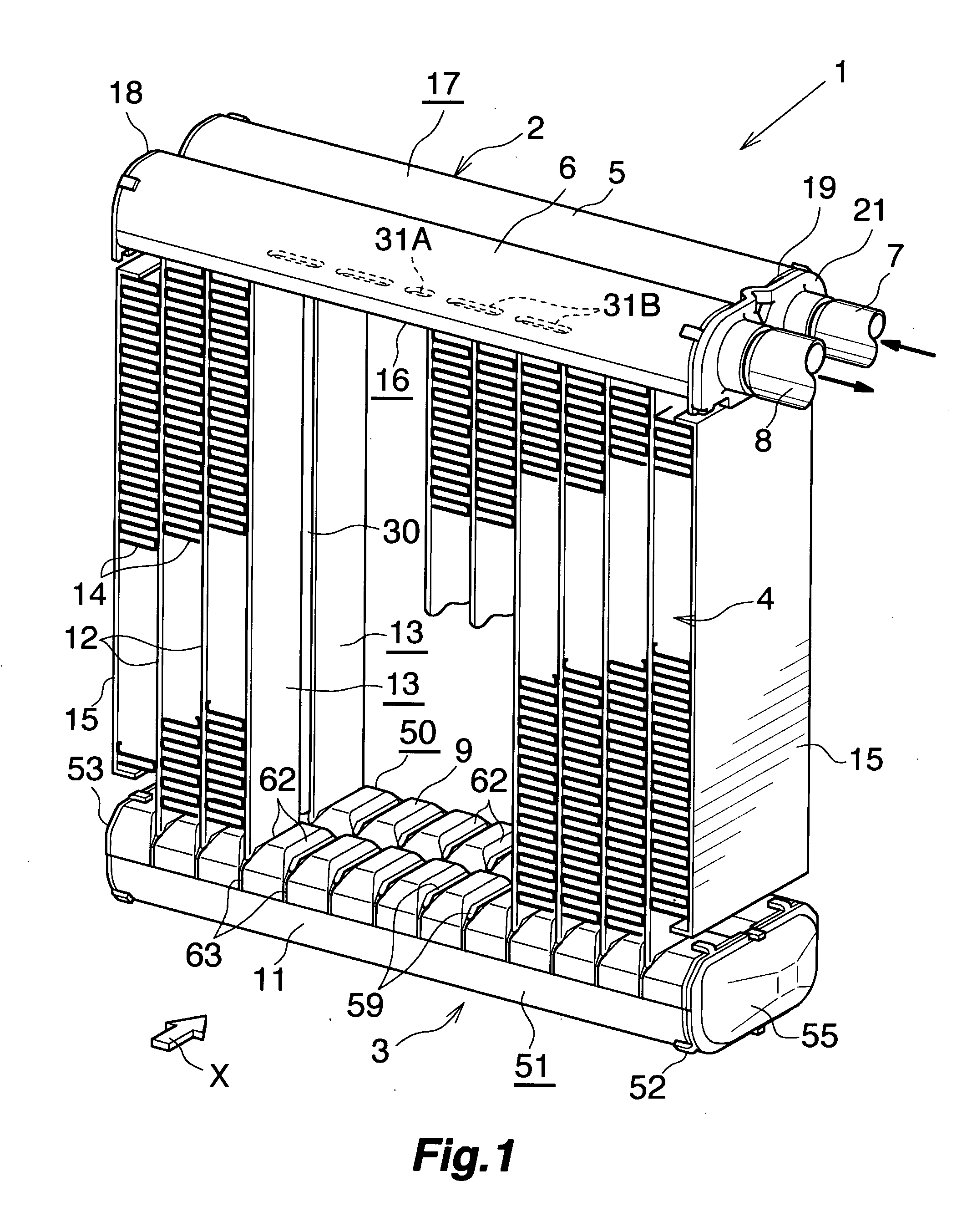
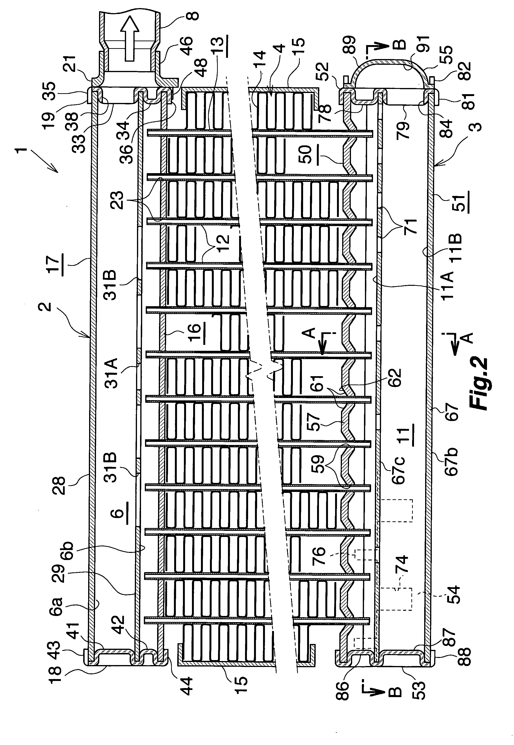
[0050]FIGS. 1 and 2 show the overall configuration of an evaporator, and FIGS. 3 to 9 show the configuration of essential portions of the evaporator. FIG. 10 shows how a refrigerant flows in the evaporator.

[0051]In FIGS. 1 and 2, the evaporator (1), which is used in a car air conditioner using a chlorofluorocarbon-based refrigerant, includes a refrigerant inlet / outlet tank (2) made of aluminum and a refrigerant turn tank (3) made of aluminum, the tanks (2) and (3) being vertically spaced apart from each other, and further includes a heat exchange core section (4) provided between the tanks (2) and (3).

[0052]The refrigerant inlet / outlet tank (2) includes a refrigerant inlet header (5) (first header) located on a side toward the front (downstream side with respect to the air flow direction) and a refrigerant outlet header (6) (second header) located on a side toward the rear (upstream side with respect to the air flow direct...

experiment example 1

[0094]A prepared test assembly was configured such that the heat exchange tubes (12), the drainage acceleration members (30), and the corrugate fins (14) were assembled as in the case of the above-described embodiment, but the refrigerant inlet / outlet tank (2) and the refrigerant turn tank (3) were not attached thereto. The heat exchange tubes (12) and the drainage acceleration members (30) have a thickness h of 1.4 mm as measured in the left-right direction; the gap (70) between the heat exchange tubes (12) and the corresponding drainage acceleration members (30) has a width w of 0.25 mm as measured in the front-rear direction; the drainage acceleration members (30) have a width of 3.5 mm as measured in the front-rear direction; the corrugate fins (14) have a fin height (H) of 8 mm; and the fin pitch (P) is 1.5 mm. Opposite end openings of the heat exchange tubes (12) and those of the drainage acceleration members (30) were closed. The test assembly was immersed in water contained ...

embodiment 2

[0097]This embodiment is shown in FIG. 12.

[0098]In Embodiment 2, the outer surface of the inner end wall with respect to the front-rear direction of the front heat exchange tube (12) and the front end surface of the drainage acceleration member (30) are in contact with each other, and the outer surface of the inner end wall with respect to the front-rear direction of the rear heat exchange tube (12) and the rear end surface of the drainage acceleration member (30) are in contact with each other. Recesses (90) are formed between the front heat exchange tube (12) and the drainage acceleration member (30) and between the rear heat exchange tube (12) and the drainage acceleration member (30) in such a manner as to be depressed inward with respect to the left-right direction from extension surfaces of the left and right side surfaces of the heat exchange tubes (12) and to extend vertically. The recesses (90) serve as drain channels (80). Preferably, the relation 0.05≦S / h≦1.5 is satisfied...


PUM


Abstract

An evaporator includes a plurality of heat exchange tubes extending vertically and arranged in rows spaced apart from each other in a front-rear direction. A drainage acceleration member extending vertically is disposed between the adjacent front and rear heat exchange tubes. A gap is present between each of the adjacent front and rear heat exchange tubes, and the drainage acceleration member disposed between the front and rear heat exchange tubes. The gaps serve as drain channels. The evaporator exhibits excellent drainage of condensed water.

Description

CROSS REFERENCE TO RELATED APPLICATIONS[0001]This application is an application filed under 35 U.S.C. § 111(a) claiming the benefit pursuant to 35 U.S.C. § 119(e)(1) of the filing date of Provisional Application No. 60 / 641,740 filed Jan. 7, 2005 pursuant to 35 U.S.C. § 111(b).TECHNICAL FIELD[0002]The present invention relates to an evaporator to be built in, for example, a car air conditioner, which is a refrigeration cycle to be mounted on an automobile.[0003]Herein and in the appended claims, the downstream side of an air flow (a side represented by arrow X in FIGS. 1 and 10, and a right-hand side in FIG. 4) is referred to as the “front,” and the opposite side as the “rear.” The upper, lower, left-hand, and right-hand sides of FIG. 2 will be referred to as “upper,”“lower,”“left,” and “right,” respectively.BACKGROUND ART[0004]Conventionally, a so-called laminated evaporator has been widely employed as an evaporator for use in a car air conditioner. In the laminated evaporator, a pl...

Claims


Application Information

Patent Timeline
Patent Type & Authority Applications(United States)
IPC IPC(8): F25B1/00F28D1/00
CPCF25B39/022F25B2500/01F28F17/005F28D1/05391F28F9/0278F25D21/14
Inventor WATANABE, SUMITAKA
Owner KEIHIN THERMAL TECH CORP
Why Eureka
Try Eureka