Bag computer computing unit panel and display panel

Active Publication Date: 2011-05-05
DALEY III CHARLES A
View PDF80 Cites 28 Cited by
  • Summary
  • Abstract
  • Description
  • Claims
  • Application Information

AI Technical Summary

Benefits of technology

[0009]A mobile computer, when closed, looks like a regular bag and can be easily mixed with any normal apparel the operator might be wearing.
[0025]As an example of the bag which forms the central holder for the bag computer components, a bag is described which has pivoting attachments consisting of flexible fabric attachment flaps matching the clamp jaws found on the display, cover, receptacle or manual character input device edge. There may be openings in the bag's front wall to allow electrical wires from the outside equipment to pass to the bag's interior. The bag's attachment flaps may be double layered with a passage to lead and cover wiring from the computer equipment through to the front wall opening and bag interior. This bag has a computing unit panel mounting structure attached to the inside of the bag front wall for holding the computing unit panel in place for electrical connection to the display and, if present, manual character input device. The computing unit panels also acts as a rigid front panel support to flatten the bag front and make the pivoting equipment store better against the bag front.
[0026]The computing unit panel may be positioned and sized to counteract any bulging of the bag due to cargo loads in the interior of the bag and allow the display panel to store in the computer equipment area on the outside surface of the bag's front wall and allow the display panel pivoting computer equipment mount to work properly. The computing unit panel may be shaped on its front surface to be complimentary to the bag front wall and / or the display panel back side.

Problems solved by technology

But, because of their small size, cannot display standard internet or Windows programming.
Standard typing is impossible and the small size limits many other computer function.
The laptop, while portable and providing for standard desktop features, is too awkward to be carried and used at the same time.
However, there is considerable set up to use this invention and, when set up for use, it is bulky and awkward.
There are also wearable computing systems where the computer can be both carried and operated at the same time.
These have the restrictions of specialized and possibly unstylish apparatuses that are unusual and must be worn.
They also support only small displays and have no storage room for sizable general cargo.

Method used


Image

  • Bag computer computing unit panel and display panel
  • Bag computer computing unit panel and display panel
  • Bag computer computing unit panel and display panel

Examples


Embodiment Construction

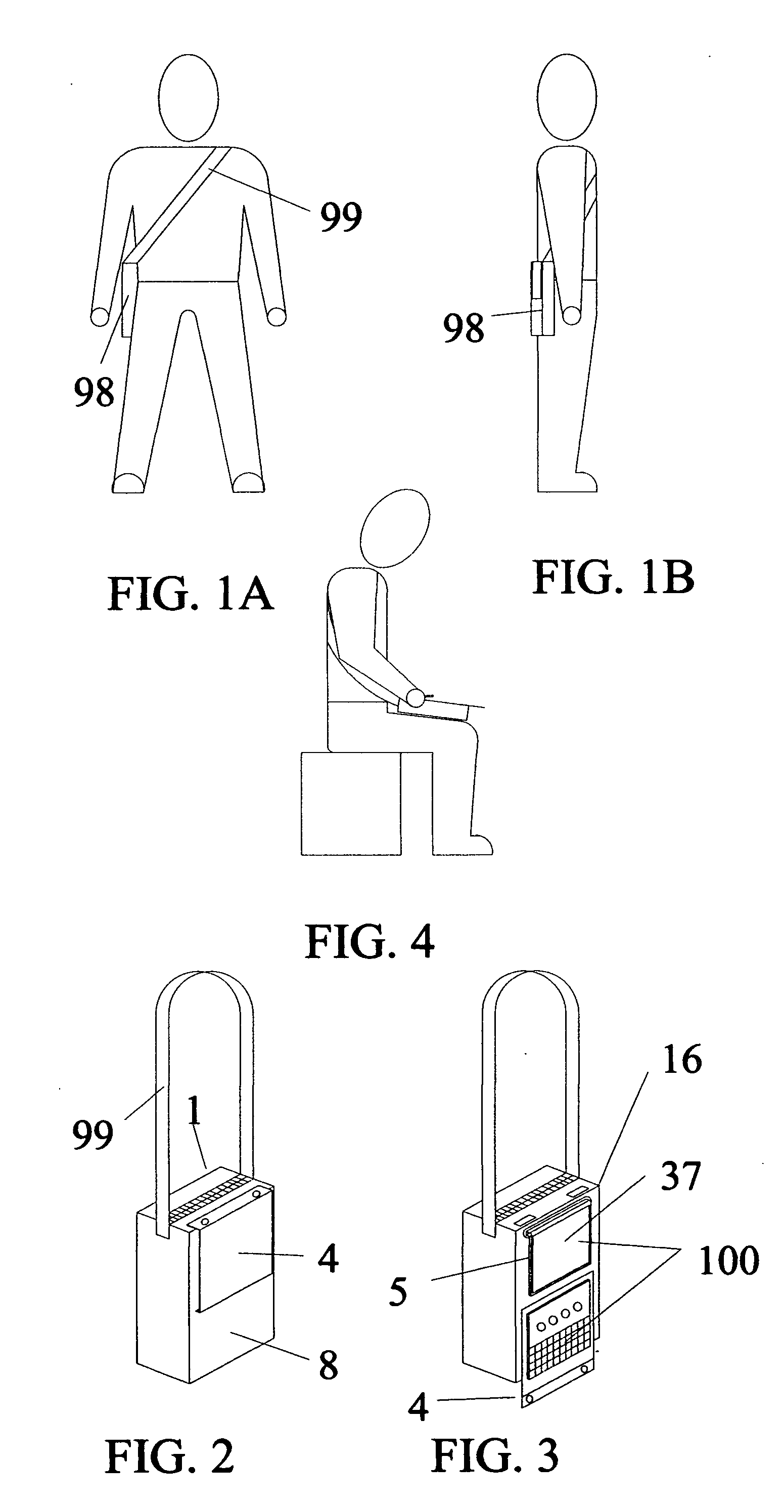
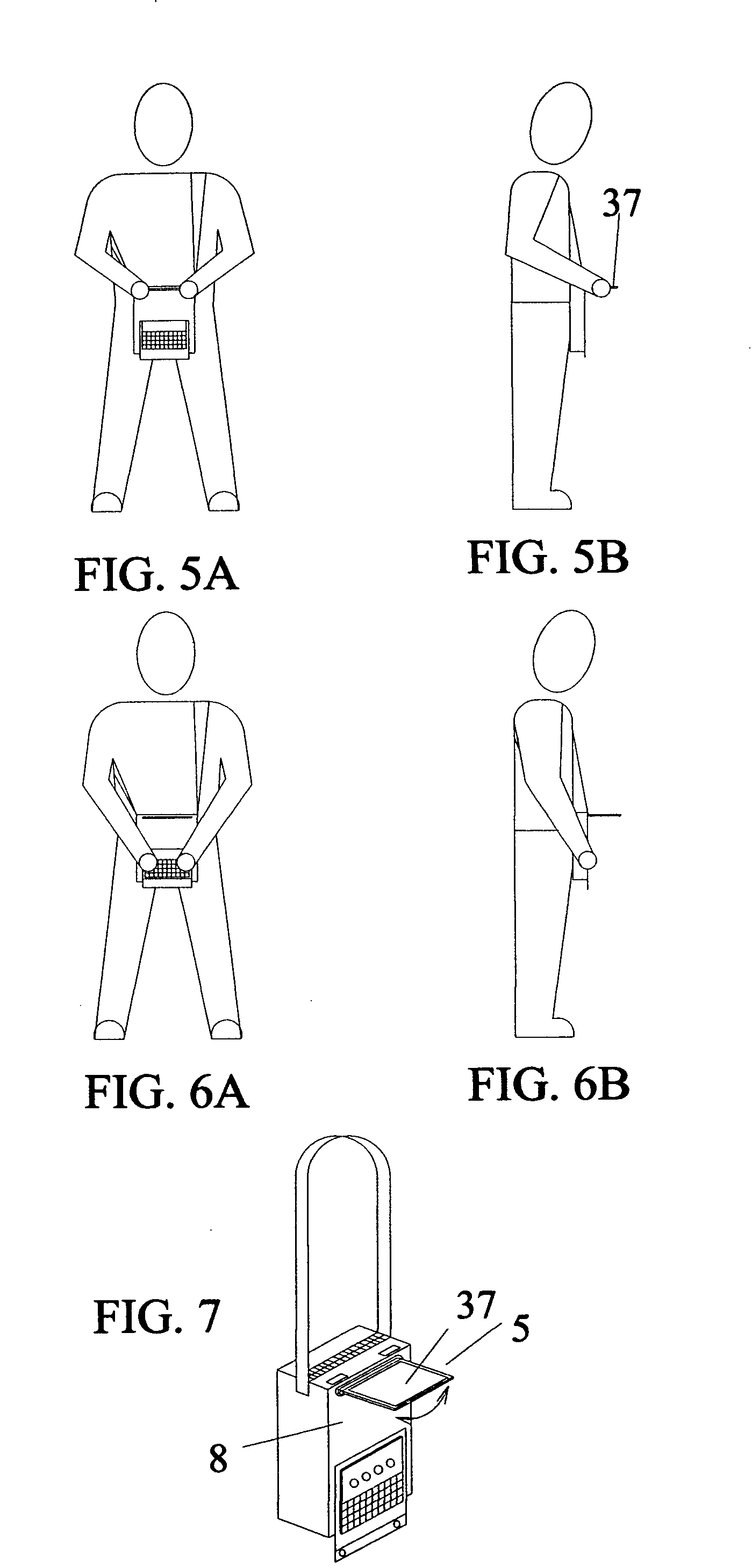
[0137]As shown in FIGS. 1A, 1B and 2, the bag computer is a combination of bag 1, computer and input / output devices that results in a mobile, self contained wearable computer. The bag is suspended from the operator body by a shoulder strap 99 so it can be carried normally or swung around in front of the operator for use. The input output devices are located on the outside of the bag's front wall so that they can be operated without accessing the interior of the bag. When the computer equipment is stored it is covered with a cover 4 on the bag's front wall 8 and the bag computer 98 appears to be a normal piece of apparel. Because the computer equipment is mounted to either the inside surface or outside surface of the bag's front wall, the majority of the bag's interior can be used for general cargo, eliminating the need to carry separate computer and general cargo bags.

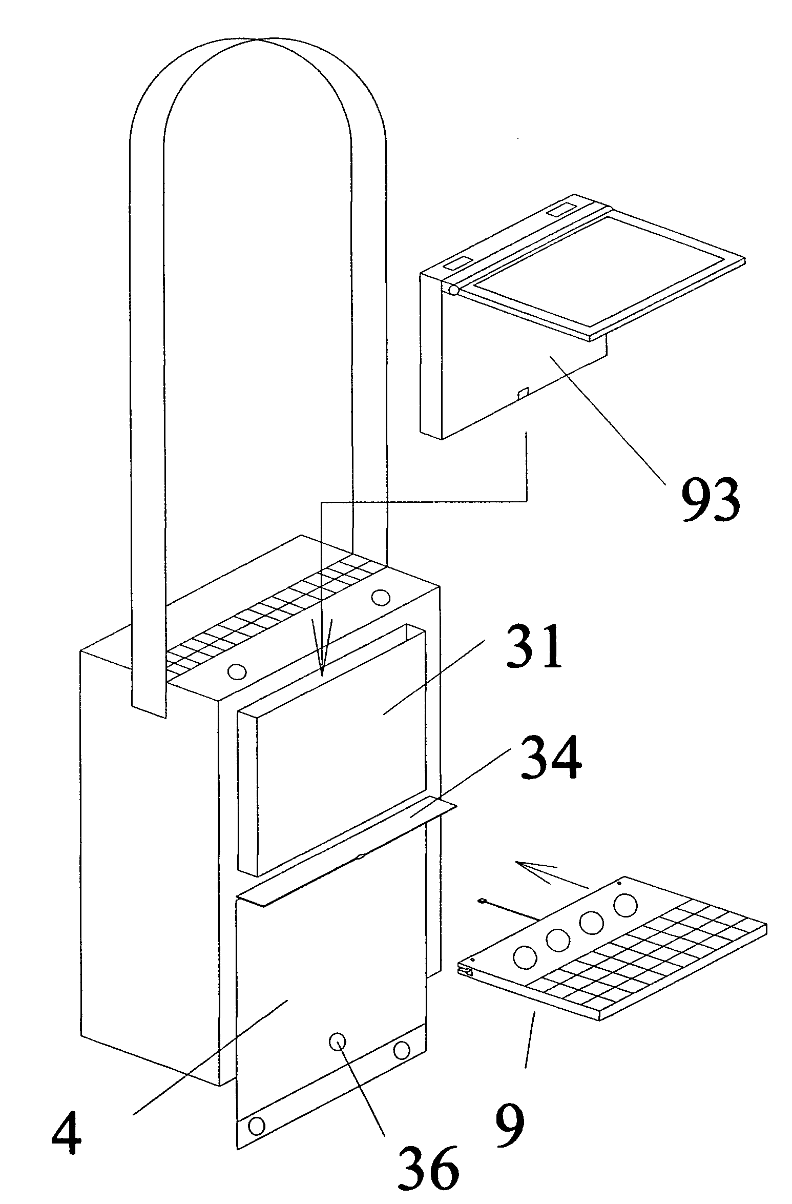
[0138]As shown in FIG. 3, when the cover 4 is opened the input / output computer equipment 100 is exposed for use. A d...


PUM


Abstract

Disclosed is a computing system including bag and computer components which allow the bag wearer to quickly access and use a computer while mobile. System components, which may vary, include: a bag adapted to attach various computer components and with a computer equipment storage area on outside front; a pivoting display panel located near the bag top front and pivoting into the storage area a computing unit panel located on the bag's inside front; a pivoting input device located on the outside bag front; a pivoting cover near the bottom of the storage area to protect the equipment stored there. The components have appropriate physical and electrical connections. The computing unit panel, in particular, may be shaped and positioned on the inside of the bag front to form a front wall support to assist in storing the display panel in the storage area on the outside of the bag front.

Description

CROSS-REFERENCE TO RELATED APPLICATIONS[0001]This application is a Continuation-In-Part and claims the filing benefit under 35 U.S.C. §120 of copending U.S. application Ser. No. 12 / 925,953, filed on Nov. 4, 2010, which is a Continuing Application of U.S. application Ser. No. 12 / 216,650, filed on Jul. 9, 2008, which is a Continuation-In-Part of U.S. application Ser. No. 11 / 796,920, filed May 1, 2007, and which is a Continuation-In-Part of U.S. application Ser. No. 11 / 799,011, filed May 1, 2007. The disclosures of all of these U.S. patent applications are incorporated herein by reference.[0002]This application is a Continuation-In-Part and claims the filing benefit under 35 U.S.C. §120 of copending U.S. application Ser. No. 12 / 216,650, filed on Jul. 9, 2008, which is a Continuation-In-Part of U.S. application Ser. No. 11 / 796,920, filed May 1, 2007, and which is a Continuation-In-Part of U.S. application Ser. No. 11 / 799,011, filed May 1, 2007. The disclosures of all of these U.S. paten...

Claims


Application Information

Patent Timeline
IPC IPC(8): G06F1/16
CPCG06F1/1628
Inventor DALEY, III, CHARLES A.
Owner DALEY III CHARLES A
Why Eureka
Try Eureka