Robot device and liquid supply device

A technology for liquid supply and robotics, applied in the direction of fluid pressure actuators, manipulators, mechanical equipment, etc., can solve problems such as no practical devices

Pending Publication Date: 2022-04-08
AISIN CORP
View PDF3 Cites 0 Cited by
  • Summary
  • Abstract
  • Description
  • Claims
  • Application Information

AI Technical Summary

Problems solved by technology

However, as a liquid supply device for supplying and discharging liquid to a fluid pressure actuator used as an artificial muscle, no device with sufficient practicality has been proposed, and a liquid supply device capable of appropriately operating a fluid pressure actuator is required.

Method used


Image

  • Robot device and liquid supply device
  • Robot device and liquid supply device
  • Robot device and liquid supply device

Examples


Embodiment Construction

[0018] Next, modes for implementing the invention of the present disclosure will be described with reference to the drawings.

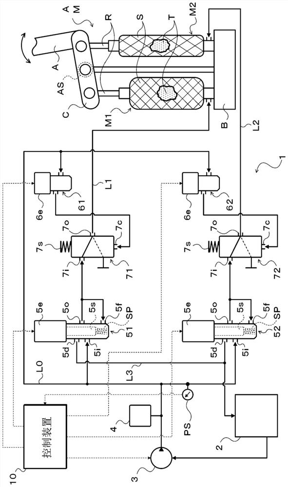
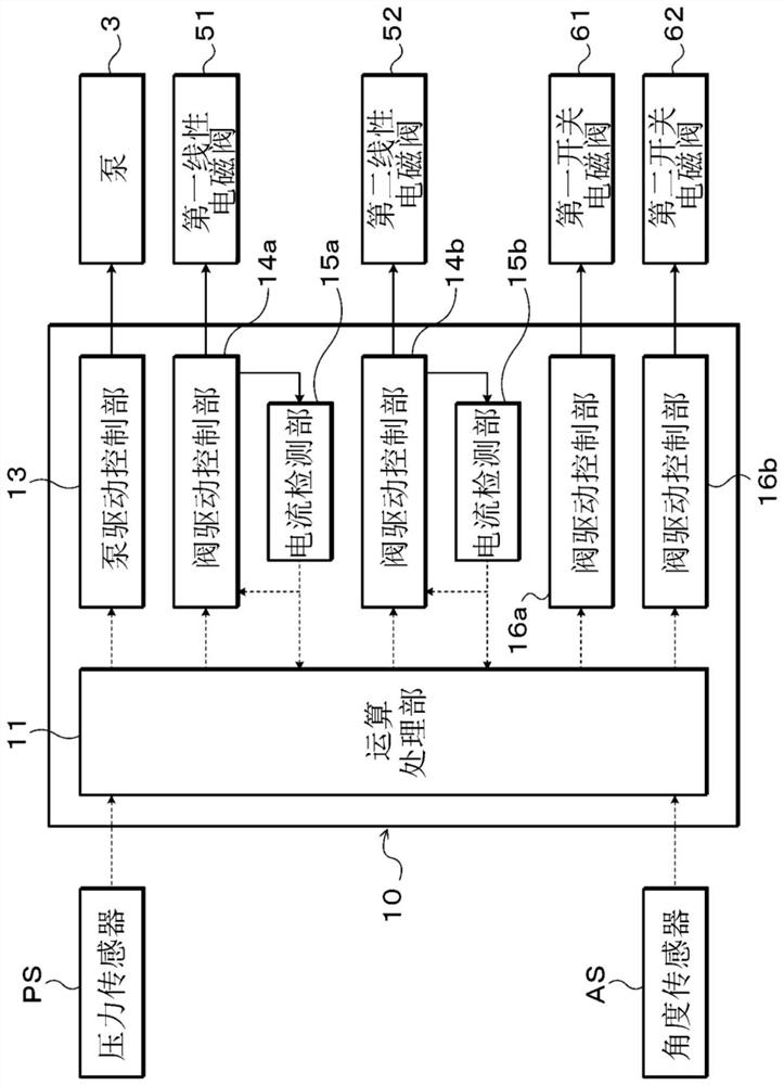
[0019] figure 1 It is a schematic configuration diagram showing the liquid supply device 1 of the present disclosure. The liquid supply device 1 shown in this figure is a driving device that hydraulically drives two hydraulic actuators M1 and M2 included in the artificial muscle unit AM to supply and discharge hydraulic oil (liquid). As shown in the figure, in addition to the two hydraulic actuators M1 and M2, the artificial muscle unit AM also includes a base part B, a connecting rod C supported by the base part B, and a Movable arm A. Furthermore, the artificial muscle unit AM together with the liquid supply device 1 constitutes, for example, a robot device of the present disclosure including a hand and a robot arm. However, the artificial muscle unit AM may also constitute a robot device, a walking robot, a wearable robot, etc. including a robot...


PUM


Abstract

The invention relates to a robot apparatus and a liquid supply apparatus. A robot device according to the present disclosure includes at least one artificial muscle that operates by receiving a supply of a liquid, and a liquid supply device that supplies and discharges the liquid to the artificial muscle, the liquid supply device including: a liquid storage unit that stores the liquid; a pressure regulating valve for regulating the pressure of the liquid from the liquid storage part and supplying the liquid to the artificial muscle; and a liquid holding unit that holds the liquid supplied to the artificial muscle in the artificial muscle in response to the occurrence of the abnormality, and enables the artificial muscle that operates by receiving the supply of the liquid to operate appropriately.

Description

technical field [0001] The present disclosure relates to a robot device including at least one artificial muscle that operates by receiving a supply of liquid, and a liquid supply device that supplies and discharges liquid to the artificial muscle. Background technique [0002] Conventionally, as a fluid pressure actuator constituting a McKibben-type artificial muscle, an actuator including an actuator main body including a cylinder that expands and contracts by fluid pressure and a sealing mechanism is known. shaped tube, and a sleeve that is a structure incorporating cords oriented in a prescribed direction and covers the outer peripheral surface of the tube, and the sealing mechanism actuates the shaft in the axial direction of the actuator body. The end of the device main body is sealed (for example, refer to Patent Document 1). In this fluid pressure actuator, a fluid can be supplied into the tubular body to expand the tubular body in the radial direction and contract ...

Claims


Application Information

Patent Timeline
IPC IPC(8): F15B20/00F15B15/10F15B11/16F15B13/06F15B1/02
CPCF15B20/00B25J9/1075G05B2219/32385G05B2219/39462B25J9/142B25J9/1615B25J9/1674B25J13/088
Inventor 兴梠怜士市川真也冈本朋也石川智己浅井雅广藤井规臣藤来将之
Owner AISIN CORP
Why Eureka
Try Eureka