Clamp for External Orthopaedic Fixing Device

a technology for fixing devices and orthopaedics, which is applied in the direction of invalid friendly devices, rod connections, prostheses, etc., can solve the problems of unusable devices, demultiplier the force transferred to the elements, and the inability to use the entire device, so as to achieve excellent and efficient distribution of the load on the bar

Inactive Publication Date: 2011-05-12
ORTHOFIX SRL
View PDF37 Cites 65 Cited by
  • Summary
  • Abstract
  • Description
  • Claims
  • Application Information

AI Technical Summary

Benefits of technology

[0023]The abovementioned technical problem is solved by a clamp of the type previously indicated and characterised in that the first attachment comprises a mobile jaw hinged, along an hinging axis perpendicular to the plane of the C-shaped section of the lateral housing, at the free end of the external arm of the first attachment and subjected to the tightening element in such a way that a tightening of said tightening element causes a pressure of the mobile jaw on the first connection bar in the direction of the internal arm, thus performing an action of restraining of the first connection bar in the lateral housing. In this way the following advantage is obtained: the transmission of the force of tightening to the connection bars is obtained by means of the independent mobile jaw.
[0026]This configuration of the external arm and of the jaw elements allows an excellent and efficient distribution of the loads on the bar.

Problems solved by technology

The clamp of the type described above, although satisfactorily performing the function for which it is designed, however has a disadvantage linked to the disadvantageous transmission of the force of tightening of the screw to the blocked element, i.e. to the bar (or bone screw or wire).
This results in a demultiplication of the force transferred to the element and, in a final analysis, in a need for the surgeon to apply a high torque to the tightening screw in order to ensure satisfactory tightening of the structure.
The clamp described here, however, has other disadvantages in relation to the prior art.
This structure causes possible difficulties for the end user, as the nut and washer elements, of limited dimensions, can easily be lost, making the entire device unusable, or be dropped, making their reassembly complicated.
Moreover the end projection with a restraining function causes a localised distribution of the load on the connection bar to be blocked, and such a localised distribution causes deformations on the same bar and poor resistance of the joint in relation to possible fatigue stresses.
However, such a configuration has the drawback that the retaining force on the bar is relatively low and not adjustable.

Method used


Image

  • Clamp for External Orthopaedic Fixing Device
  • Clamp for External Orthopaedic Fixing Device
  • Clamp for External Orthopaedic Fixing Device

Examples


Embodiment Construction

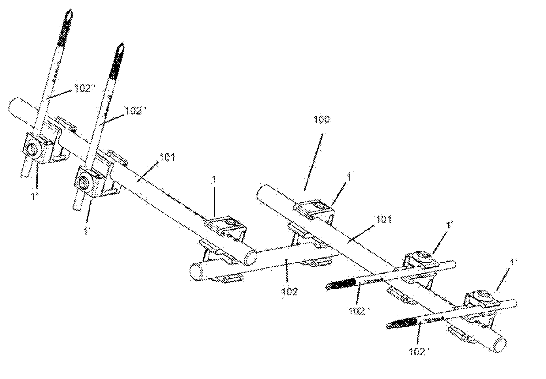
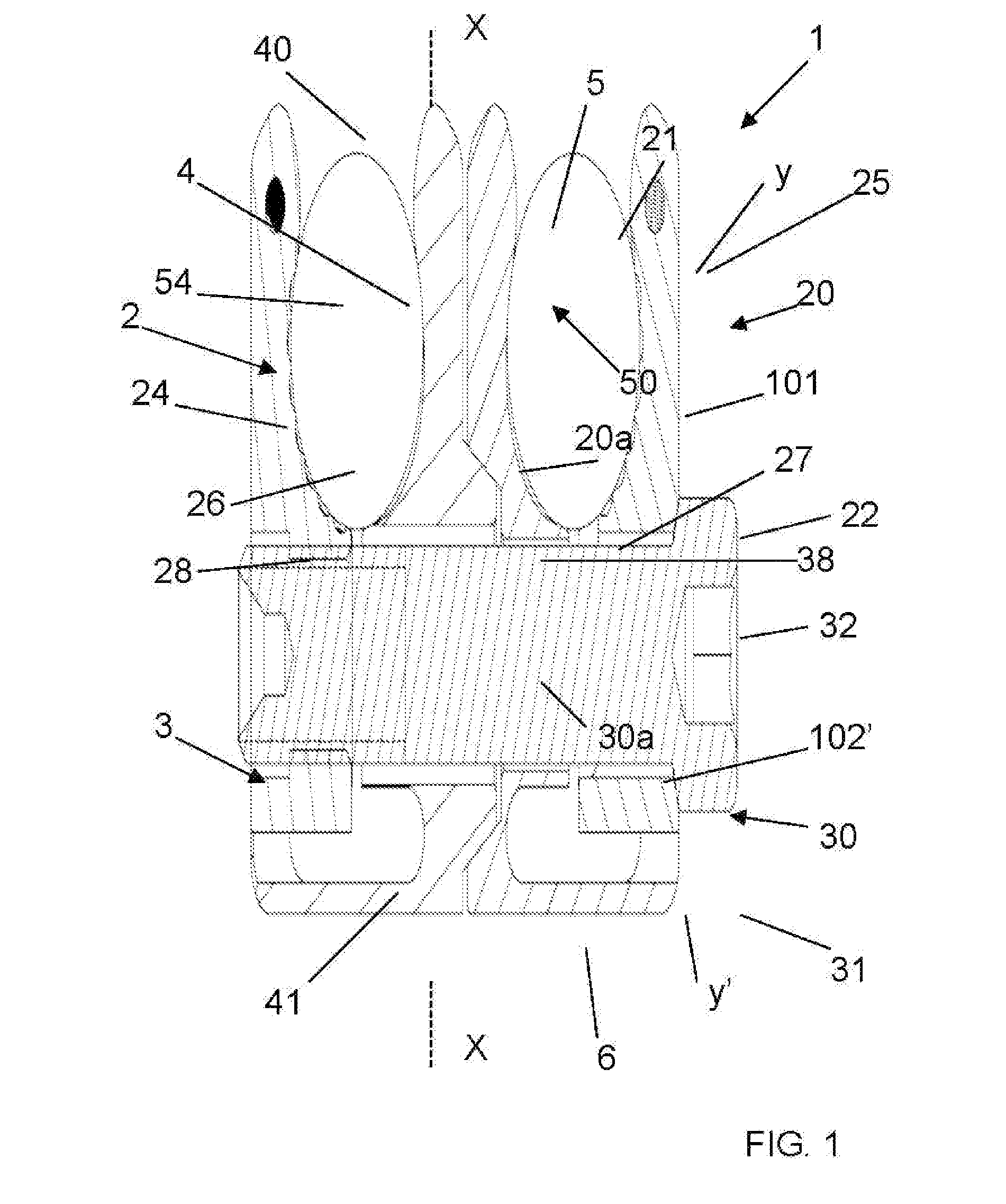
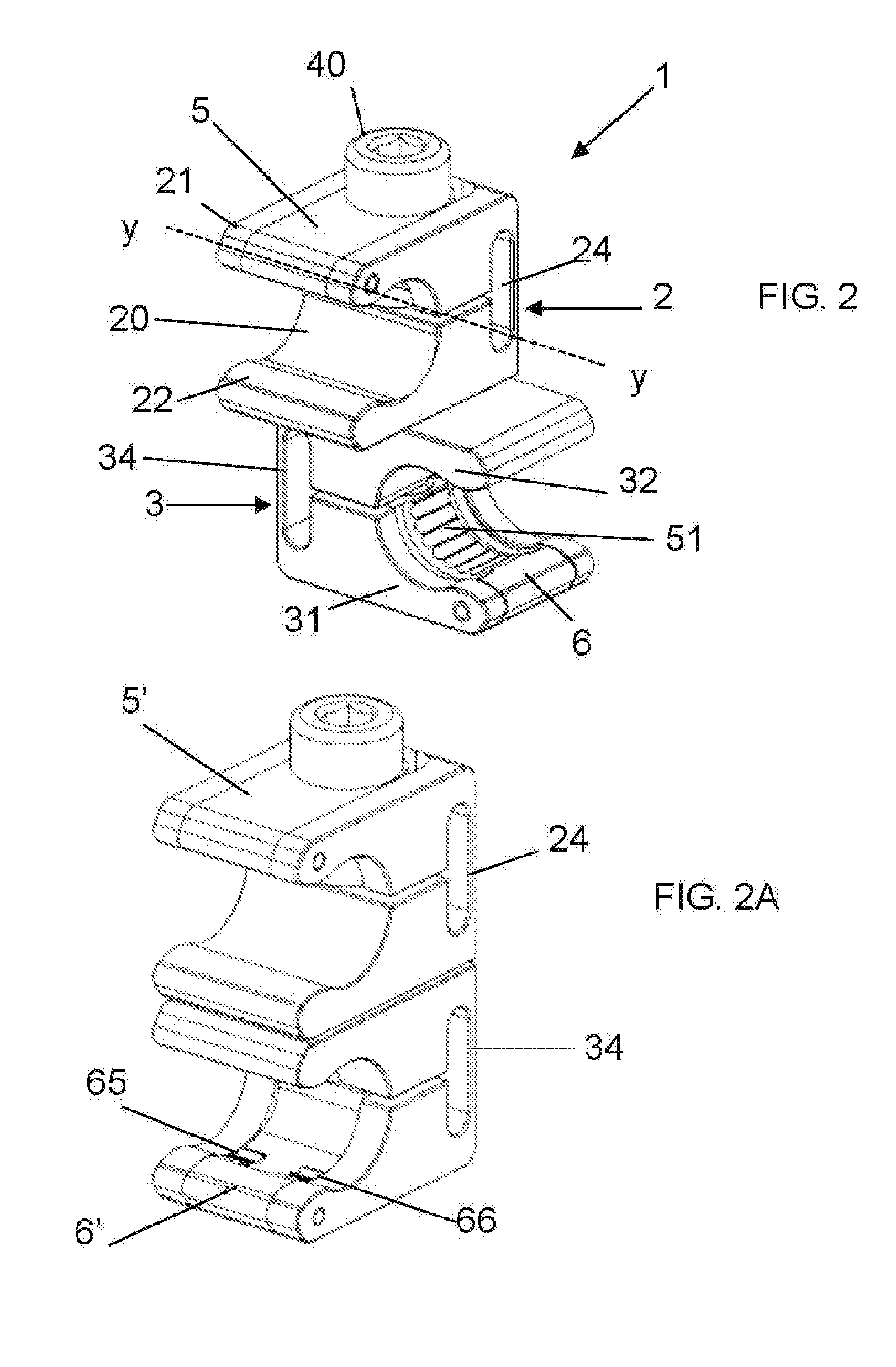
[0037]Referring to the accompanying drawings, the clamp according to the invention is denoted by reference numerals 1, 1′ and 1″ according to the reference embodiment.

[0038]This clamp 1; 1′; 1″, as explained in the previous discussion on the prior art, is structured to act as a connection element of an orthopaedic external fixator 100, more particularly of a rapid fixator of the type illustrated in FIG. 6. This function of the clamp 1, 1′, 1″ can also be performed temporarily.

[0039]The clamp 1; 1′; 1″ is meant to create in a rapid and effective manner a temporary rigid connection between a first connection bar 101 and a second component 102; 102′ of the fixator 100, for example as shown in FIG. 6. In this case three different embodiments of the invention are described in detail, in which the clamp is designed to connect the first connection bar 101 to second components of a different type: in the first embodiment (bar-bar clamp 1) the second component is a second connection bar 102 ...


PUM


Abstract

A clamp (1; 1′; 1″) for orthopaedic external fixator (100), practical and safe to use, comprising a first attachment (2), provided with a pair of arms respectively internal (22) and external (21) defining one with the other a lateral housing (20) with C-shaped section for housing a first connection bar (101) and comprising a mobile jaw (5) hinged on its external arm (21); a second attachment (3; 3′; 3″) for allowing the connection of the clamp (1; 1′; 1″) to a second component (102; 102′) of the orthopaedic external fixator (100); a tightening element (4), at least partially threaded, which traverses and connects the first and the second attachment (2, 3; 3′; 3″) along an axis of rotation (x) and whereto the mobile jaw (5) is subjected, the tightening of the tightening element (4) bringing the clamp from a loosened configuration, at which the two attachments (2, 3; 3′; 3″) are reciprocally rotatable around the axis of rotation (x), to a tightened configuration, at which the relative orientation of the attachments (2, 3; 3′; 3″) is blocked; causing a pressure of the mobile jaw (5) on the first connection bar (101) in the direction of the internal arm (22), performing therefore an action of restraining of the first connection bar (101) in the lateral housing (20).

Description

FIELD OF APPLICATION[0001]The present invention relates to a clamp for orthopaedic applications, more particularly intended for binding, especially temporarily, the component elements of an external fixing system.[0002]More particularly the invention relates to a clamp for an orthopaedic external fixator, comprising:[0003]a first attachment, provided with two arms respectively external and internal in relation to the overall structure of the clamp, defining one with the other a lateral housing with C-shaped section suitable for housing a first connection bar of the orthopaedic external fixator;[0004]a second attachment designed to allow the connection of the clamp to a second component of the orthopaedic external fixator, other than the first connection bar;[0005]a tightening element, at least partially threaded, which traverses and connects the first and the second attachment along an axis of rotation transverse to the extension of the external and internal arms; the tightening of ...

Claims


Application Information

Patent Timeline
Patent Type & Authority Applications(United States)
IPC IPC(8): A61B17/00
CPCA61B17/645A61B17/6466F16B7/0493F16B7/0433F16B2/12A61B17/60A61B17/66A61B17/86A61F5/01
Inventor VENTURINI, DANIELEBAGNASCO, MARA
Owner ORTHOFIX SRL
Why Eureka
Try Eureka