Offshore energy harvesting, storage, and power generation system

a technology of energy harvesting and power generation system, applied in sustainable manufacturing/processing, vessel parts, vessel construction, etc., can solve the problems of wind and energy harvesting system, difficult to meet the needs of customers, and often with great environmental damage, so as to reduce fuel consumption, increase overall efficiency, and reduce emissions

Active Publication Date: 2011-09-08
MASSACHUSETTS INST OF TECH
View PDF16 Cites 54 Cited by
  • Summary
  • Abstract
  • Description
  • Claims
  • Application Information

AI Technical Summary

Benefits of technology

[0016]A still further object of the invention is to load-level on-shore power plants for increased overall efficiency, reduced emissions, and reduced fuel usage.
[0017]A still further object of the invention is to store hydrocarbons in the vicinity of undersea wells during hurricane shut-in procedures and during potential well leaks, allowing more rapid retrieval of the hydrocarbons once oil platform / rig operations are allowed to continue safely.

Problems solved by technology

Wind and energy harvesting systems suffer from the problem of what to do when the winds are calm or wind speed varies significantly.
The resulting variation of input from the wind energy source to the grid can cause trouble if the wind energy source makes up more than a few percent of the total capacity of the grid.
Similarly, when the winds have high amplitude and the electric generators are running at maximum power, the excess power put into the grid can also cause troubles if it is not needed.
It is well known that on land, excess wind power can be used to pump water uphill to a reservoir; however, this approach is often done with great environmental damage because the tops of mountains must be removed, or rivers dammed.
Furthermore, water is pumped uphill into an open reservoir, and much is lost to evaporation.
However, this is not the case when turbines are placed far offshore, where the wind is fairly regular.
During “shut-in” times production ceases which results in lost present-value profits during that period.
However, a tropical storm required evacuation of the ships collecting the oil and oil continued to leak while personnel evacuated the area.

Method used


Image

  • Offshore energy harvesting, storage, and power generation system
  • Offshore energy harvesting, storage, and power generation system
  • Offshore energy harvesting, storage, and power generation system

Examples


Embodiment Construction

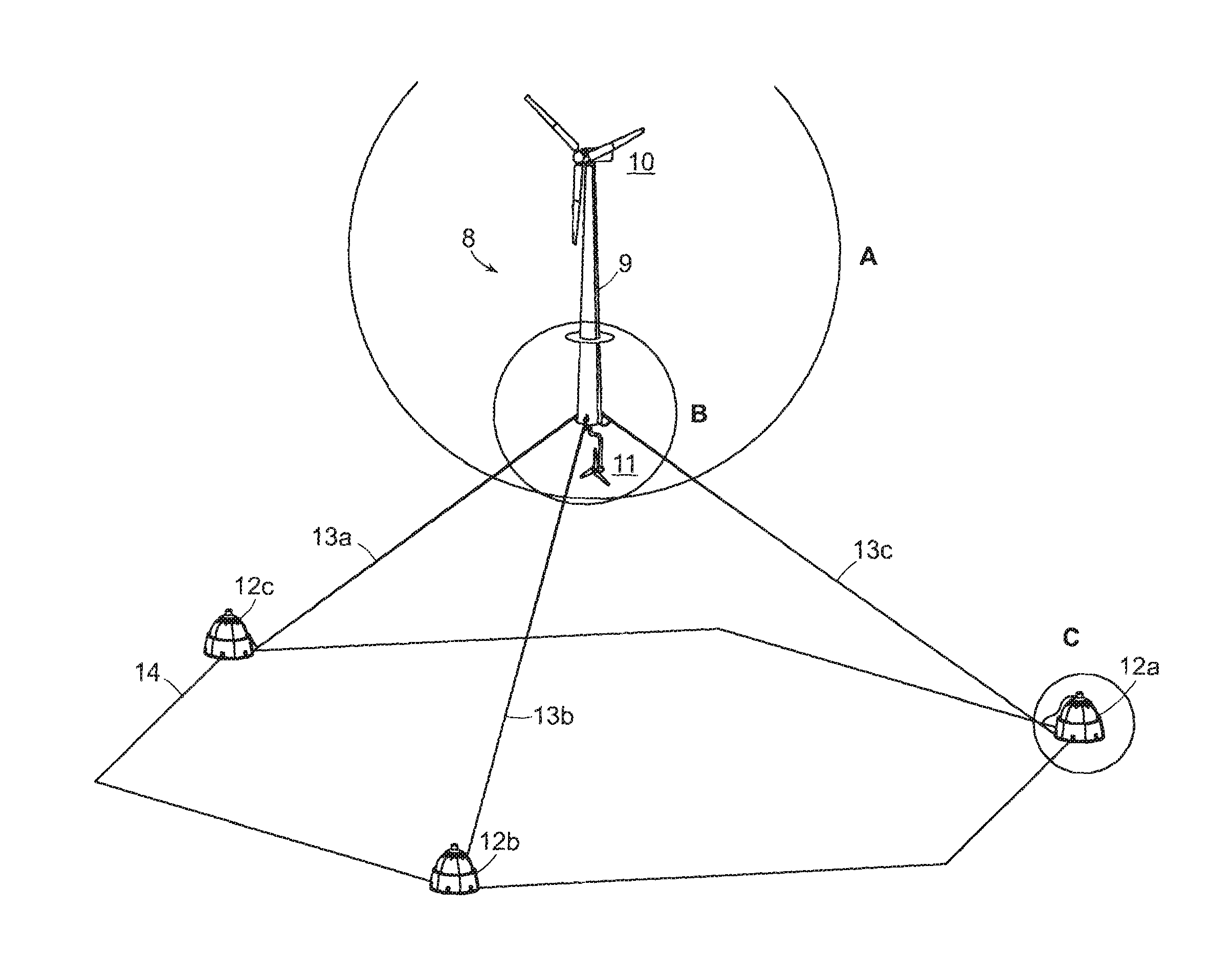
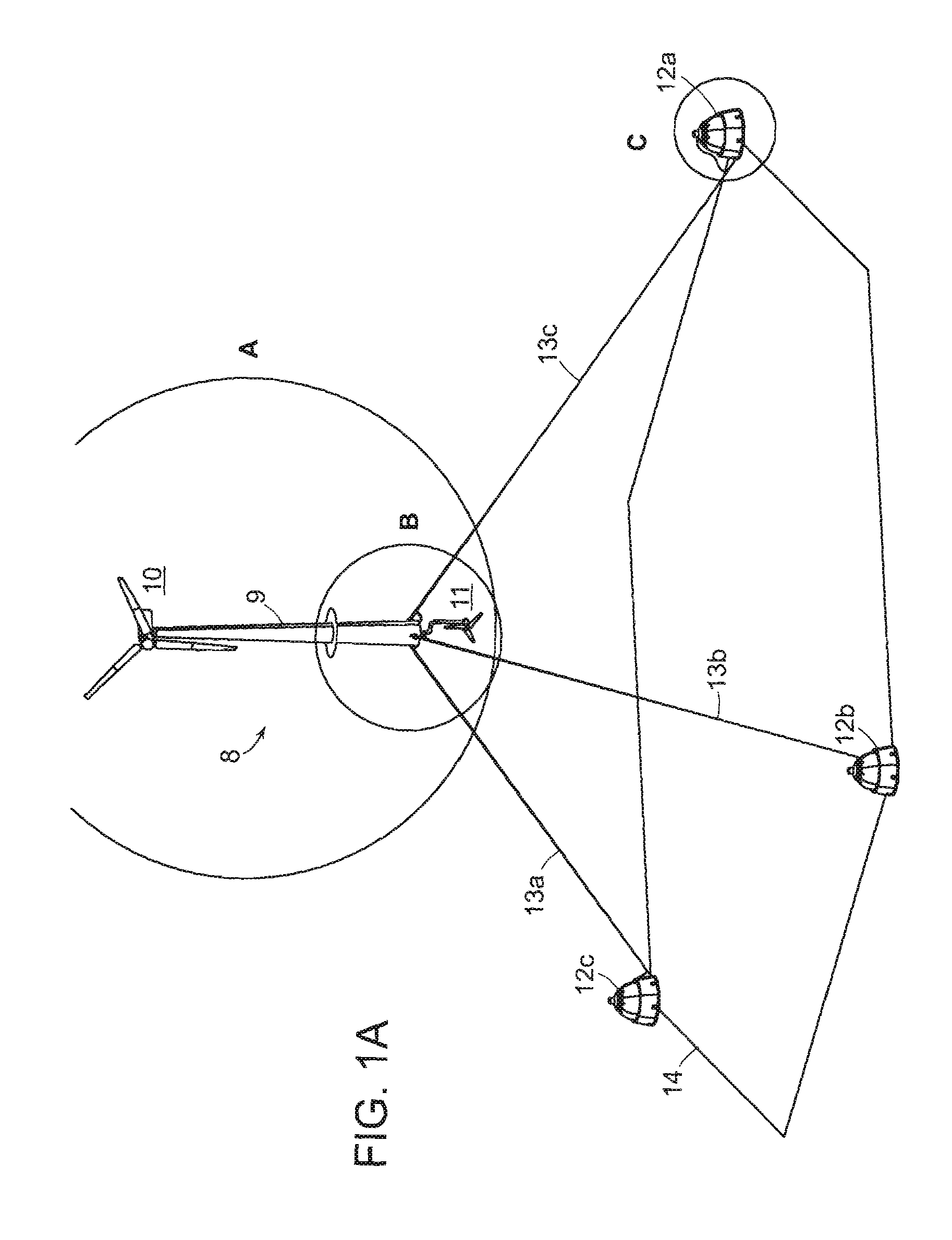
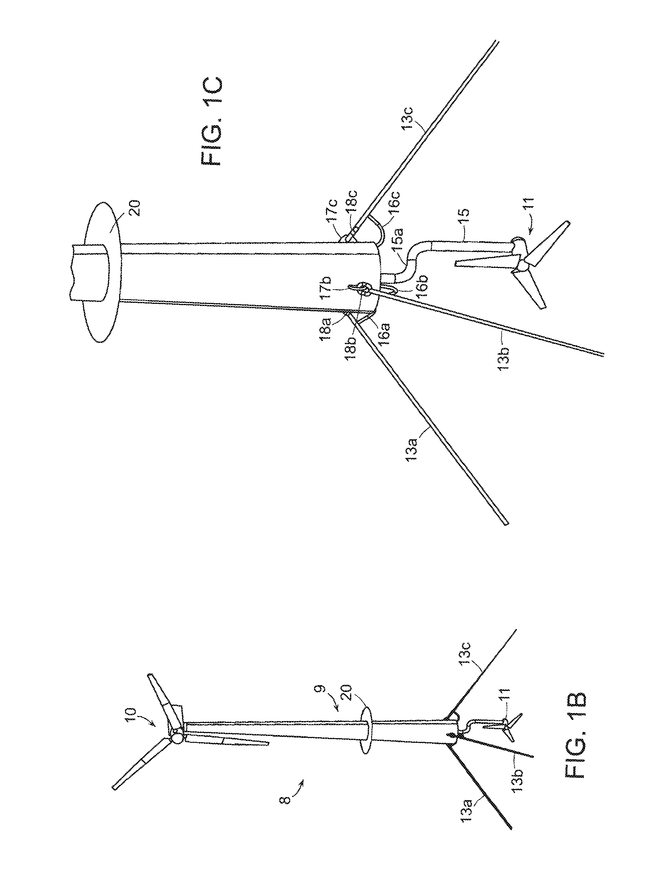
[0045]The present invention relates to a system for harvesting wind and ocean current energy offshore and storing it and / or converting it to electrical energy for transmission to shore. Supporting a large floating wind turbine in deep water requires mooring a floating structure (e.g., a large spar buoy) against large waves and high winds. Mooring lines run from the floating wind turbine to heavy deadweight anchors on the seafloor. The invention herein replaces heavy deadweight anchors with deadweight ballasted chambers from which water can be pumped to provide energy storage in the form of a void near the seafloor. Water flowing through a turbine back into the pumped-out void is then used to generate usable power. An analogy is a pumped hydroelectric system, such as commonly used at the base of onshore dams which is used to pump water into a lake to store energy, and it generates electricity by letting water flow past a turbine.

[0046]FIGS. 1a through 5c describe a early embodiment o...


PUM


Abstract

A system for harvesting, storing, and generating energy, that includes floating structure supporting machinery to extract energy from wind, waves, surface generators, or currents. At least one energy storage and power generating unit is anchored to the seafloor and adapted to tether the floating structure to the unit. The unit includes an internal chamber into which water flows through a hydroelectric turbine to generate electrical energy. A pump is provided, powered by energy from the floating structure machinery, to evacuate water from the unit and a control system directs power from the machinery to pump water out of the unit during periods of excess energy extraction by the machinery and to allow water to flow into the chamber through the hydroelectric turbine to generate electrical energy during periods of lower energy extraction by the machinery. The same internal chamber design can be utilized to store hydrocarbons in the vicinity of undersea wellheads during “shut-in” procedures when the wellhead would otherwise be secured.

Description

[0001]This application claims priority to provisional application Ser. No. 61 / 311,478 filed on Mar. 8, 2010, the contents of which are incorporated herein by reference.STATEMENT REGARDING FEDERALLY FUNDED RESEARCH[0002]No federal funds were used in the development of this invention.FIELD OF THE INVENTION[0003]This invention relates to a system for mooring floating offshore wind turbines and storing some of the energy harvested for producing electric power on demand during low wind and / or peak power demand periods.BACKGROUND OF THE INVENTION[0004]Wind and energy harvesting systems suffer from the problem of what to do when the winds are calm or wind speed varies significantly. The resulting variation of input from the wind energy source to the grid can cause trouble if the wind energy source makes up more than a few percent of the total capacity of the grid. Similarly, when the winds have high amplitude and the electric generators are running at maximum power, the excess power put in...

Claims


Application Information

Patent Timeline
Patent Type & Authority Applications(United States)
IPC IPC(8): H02J3/38F03B13/14F03D9/02B65D88/00
CPCF03B13/06F03B13/10F03B13/12F03D9/001F03D9/008F03D9/02Y02E10/72F05B2240/95F05B2240/96Y02E10/22Y02E10/38Y02E60/17F05B2240/93F03D9/10F03D13/25B63B21/27B63B21/50B63B35/44B63B2021/505B63B2035/446B63B2035/4466Y02E10/727F03D9/28F03D9/255F03D9/11Y02E10/20Y02E10/30Y02E60/16Y02P80/10Y02E70/30
Inventor SLOCUM, ALEXANDER H.FENNELL, GREGORY E.GREENLEE, ALISON S.
Owner MASSACHUSETTS INST OF TECH
Why Eureka
Try Eureka